4-16 Torque Limit Motor Mode
Range: Function:
110
%*
[ 0
-
1000.0
%]
Enter the maximum torque limit for motor
operation. The torque limit is active in the
speed range up to and including the rated
motor speed set in 1-25 Motor Nominal Speed.
To protect the motor from reaching the
stalling torque, the default setting is 1.1 x the
rated motor torque (calculated value). See
also 14-25 Trip Delay at Torque Limit for
further details.
If a setting in 1-00 Configuration Mode to
1-28 Motor Rotation Check is changed,
4-16 Torque Limit Motor Mode is not automat-
ically reset to the default setting.
4-17 Torque Limit Generator Mode
Range: Function:
100
%*
[ 0 -
1000.0
%]
Enter the maximum torque limit for
generator mode operation. The torque limit
is active in the speed range up to and
including the rated motor speed (1-25 Motor
Nominal Speed). Refer to 14-25 Trip Delay at
Torque Limit for further details.
If a setting in 1-00 Configuration Mode to
1-28 Motor Rotation Check is changed,
4-17 Torque Limit Generator Mode is not
automatically reset to the default settings.
4-18 Current Limit
Range: Function:
Size
related*
[ 1.0 -
1000.0
%]
Enter the current limit for motor and
generator operation. To protect the motor
from reaching the stalling torque, the
default setting is 1.1 x the rated motor
current (set in 1-24 Motor Current). If a
setting in 1-00 Configuration Mode to
1-28 Motor Rotation Check is changed,
4-16 Torque Limit Motor Mode to
4-18 Current Limit are not automatically
reset to the default settings.
4-19 Max Output Frequency
Range: Function:
Size
related*
[ 1
-
1000.0
Hz]
Enter
the maximum output frequency
value. 4-19 Max Output Frequency specifies
the absolute limit on the frequency
converter output frequency for improved
safety in applications where accidental
over-speeding must be avoided. This
absolute limit applies to all configurations
and is independent of the setting in
1-00 Configuration Mode. This parameter
cannot be adjusted while the motor is
running.
4-19 Max Output Frequency
Range: Function:
When 1-10
Motor Construction
is set to [1]
PM non salient SPM the maximum value is
limited to 300 Hz.
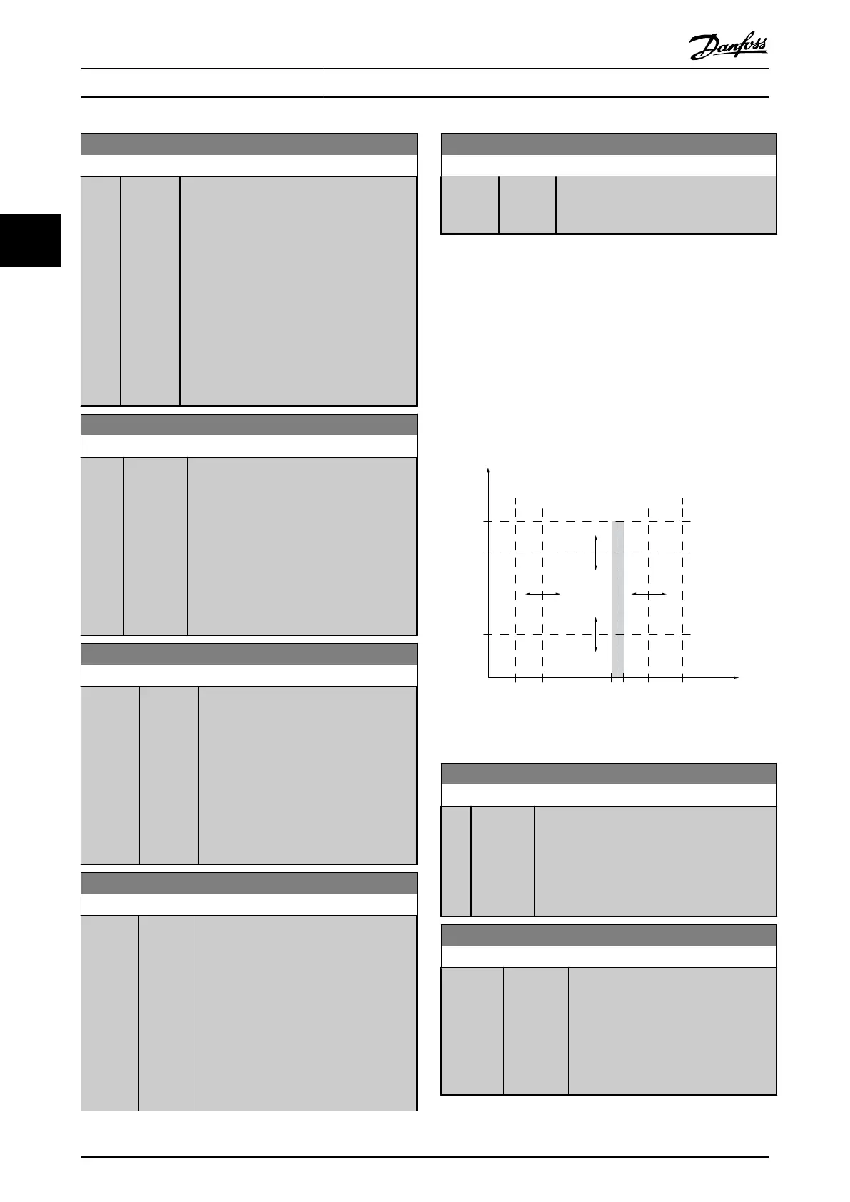
3.6.3 4-5* Adj. Warnings
Define adjustable warning limits for current, speed,
reference
and feedback.
NOTE
Not
visible in display, only in .
Warnings are shown on display, programmed output or
serial
bus.
130BA064.10
(P 4-18)
(P 4-51)
(P 4-50)
(P 4-11) (P 4-53)(P 4-52) (P 4-13)
I
HIGH
I
LOW
n
LOW
n
HIGH
n
motor
I
motor
REF
ON REF
IN RANGE
I
LIM
n
MAX
n
MIN
[RPM]
Illustration 3.20
4-50 Warning Current Low
Range: Function:
0 A* [ 0
- par.
4-51
A]
Enter the I
LOW
value. When the motor current
falls below this limit (I
LOW
), the display reads
CURRENT LOW. The signal outputs can be
programmed to produce a status signal on
terminal 27 or 29 and on relay output 01 or
02. Refer to Illustration 3.20.
4-51 Warning Current High
Range: Function:
Size
related*
[ par. 4-50
-
par.
16-37 A]
Enter the I
HIGH
value. When the motor
current exceeds this limit (I
HIGH
), the
display reads CURRENT HIGH. The signal
outputs can be programmed to
produce a status signal on terminal 27
or 29 and on relay output 01 or 02.
Refer to Illustration 3.20.
Parameter Description
VLT
®
Refrigeration Drive Programming Guide
56 MG16H102 - VLT
®
is a registered Danfoss trademark
33
 Loading...


