This shows a typical Air Handling Unit (AHU). As can be
seen,
the addition of the Analog I/O option offers the
possibility to control all of the functions from the
frequency converter, such as inlet-, return- and excaust
dampers or heating/cooling coils with temperature and
pressure measurements being read by the frequency
converter.
NOTE
The
maximum current for the analog outputs 0-10 V is 1
mA.
NOTE
Where
Live Zero Monitoring is used, it is important that
any analog inputs not being used for the frequency
controller, i.e. being used as of the Building Management
System decentral I/O, should have their Live Zero function
disabled.
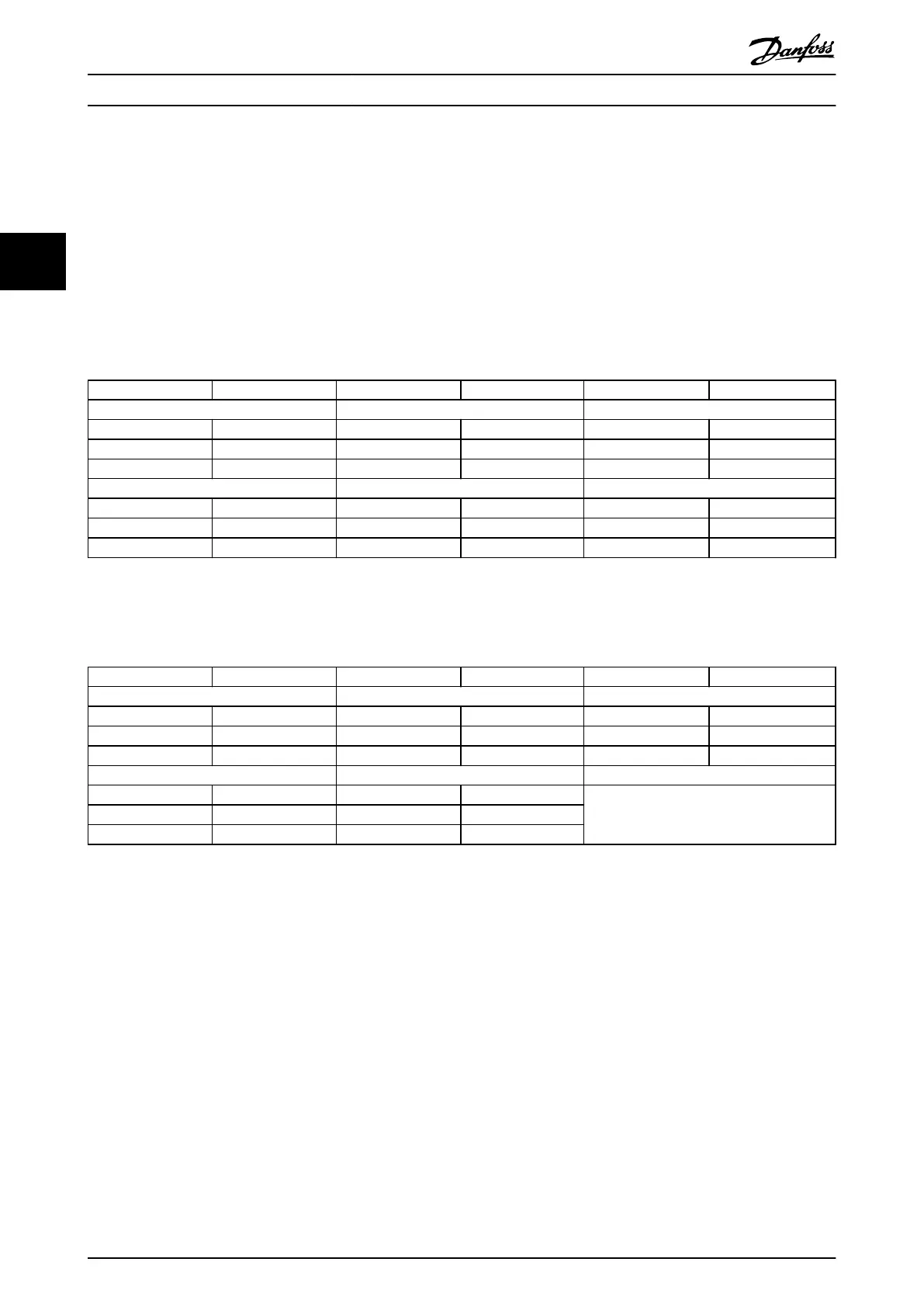
Terminal Parameters Terminal Parameters Terminal Parameters
Analog inputs Analog inputs Relays
X42/1 26-00, 26-1* 53 6-1* Relay 1 Term 1, 2, 3 5-4*
X42/3 26-01, 26-2* 54 6-2* Relay 2 Term 4, 5, 6 5-4*
X42/5 26-02, 26-3*
Analog outputs Analog output
X42/7 26-4* 42 6-5*
X42/9 26-5*
X42/11 26-6*
Table 3.28 Relevant Parameters
It is also possible to read the analog inputs, write to the
analog
outputs and control the relays, using communi-
cation via the serial bus. In this instance, these are the
relevant parameters.
Terminal Parameters Terminal Parameters Terminal Parameters
Analog inputs (read) Analog inputs (read) Relays
X42/1 18-30 53 16-62 Relay 1 Term 1, 2, 3 16-71
X42/3 18-31 54 16-64 Relay 2 Term 4, 5, 6 16-71
X42/5 18-32
Analog outputs (write) Analog output (write)
X42/7 18-33 42 6-53 NOTE! The relay outputs must be enabled via
Control
Word Bit 11 (Relay 1) and Bit 12
(Relay 2)
X42/9 18-34
X42/11 18-35
Table 3.29 Relevant Parameters
Setting of on-board Real Time Clock.
The
Analog I/O option incorporates a real time clock with
battery back-up. This can be used as back up of the clock
function included in the frequency converter as standard.
See section Clock Settings, parameter group 0-7*.
The Analog I/O option can be used for the control of
devices such as actuators or valves, using the Extended
Closed loop facility, thus removing control from the
Building Management System. See 3.16 Main Menu -
Extended Closed Loop - Group 21. There are three
independent closed loop PID controllers.
Parameter Description
VLT
®
Refrigeration Drive Programming Guide
158 MG16H102 - VLT
®
is a registered Danfoss trademark
33
 Loading...


