Analog inputs
Number of analog inputs 2
Terminal number 53, 54
Modes Voltage or current
Mode select Switches A53 and A54
Voltage mode Switch A53/A54=(U)
Voltage level 0 V to 10 V (scaleable)
Input resistance, R
i
approx. 10 kΩ
Max. voltage ±20 V
Current mode Switch A53/A54=(I)
Current level 0/4 to 20 mA (scaleable)
Input resistance, R
i
approx. 200 Ω
Max. current 30 mA
Resolution for analog inputs 10 bit (+sign)
Accuracy of analog inputs Max. error 0.5% of full scale
Bandwidth 100 Hz
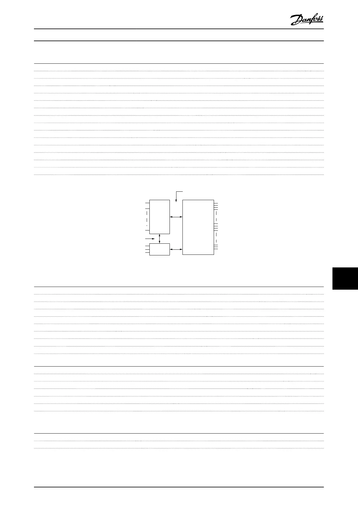
The analog inputs are galvanically isolated from the supply voltage (PELV) and other high-voltage terminals.
Mains
Functional
isolation
PELV isolation
Motor
DC-Bus
High
voltage
Control
+24V
RS485
18
37
130BA117.10
Illustration 11.1 PELV Isolation
Pulse inputs
Programmable pulse inputs 2
Terminal number pulse 29, 33
Max. frequency at terminal, 29, 33 110 kHz (Push-pull driven)
Max. frequency at terminal, 29, 33 5 kHz (open collector)
Min. frequency at terminal 29, 33 4 Hz
Voltage level see chapter 11.2.1 Digital Inputs
Maximum voltage on input 28 V DC
Input resistance, R
i
approx. 4 kΩ
Pulse input accuracy (0.1-1 kHz) Max. error: 0.1% of full scale
Analog output
Number of programmable analog outputs 1
Terminal number 42
Current range at analog output 0/4-20 mA
Max. resistor load to common at analog output 500 Ω
Accuracy on analog output Max. error: 0.8% of full scale
Resolution on analog output 8 bit
The analog output is galvanically isolated from the supply voltage (PELV) and other high-voltage terminals.
Control card, RS-485 serial communication
Terminal number 68 (P,TX+, RX+), 69 (N,TX-, RX-)
Terminal number 61 Common for terminals 68 and 69
The RS-485 serial communication circuit is functionally seated from other central circuits and galvanically isolated from the
supply voltage (PELV).
Specifications
Operating Instructions
MG16J202 Danfoss A/S © Rev. 05/2014 All rights reserved. 99
11 11

 Loading...


