211
[8.3]
623
[24.5]
148
[5.8]
280
[11.0]
346
[13.6]
420
[16.5]
1051
[41.4]
1107
[43.6]
857
[33.7]
130
[5.1]
320
[12.6]
271
[10.7]
20
[0.8]
18
[0.7]
379
[14.9]
96
[3.8]
879
[34.6]
142
[5.6]
107
[4.2]
213
[8.4]
1050
[41.3]
718
[28.3]
130BC516.11
1
4
2
3
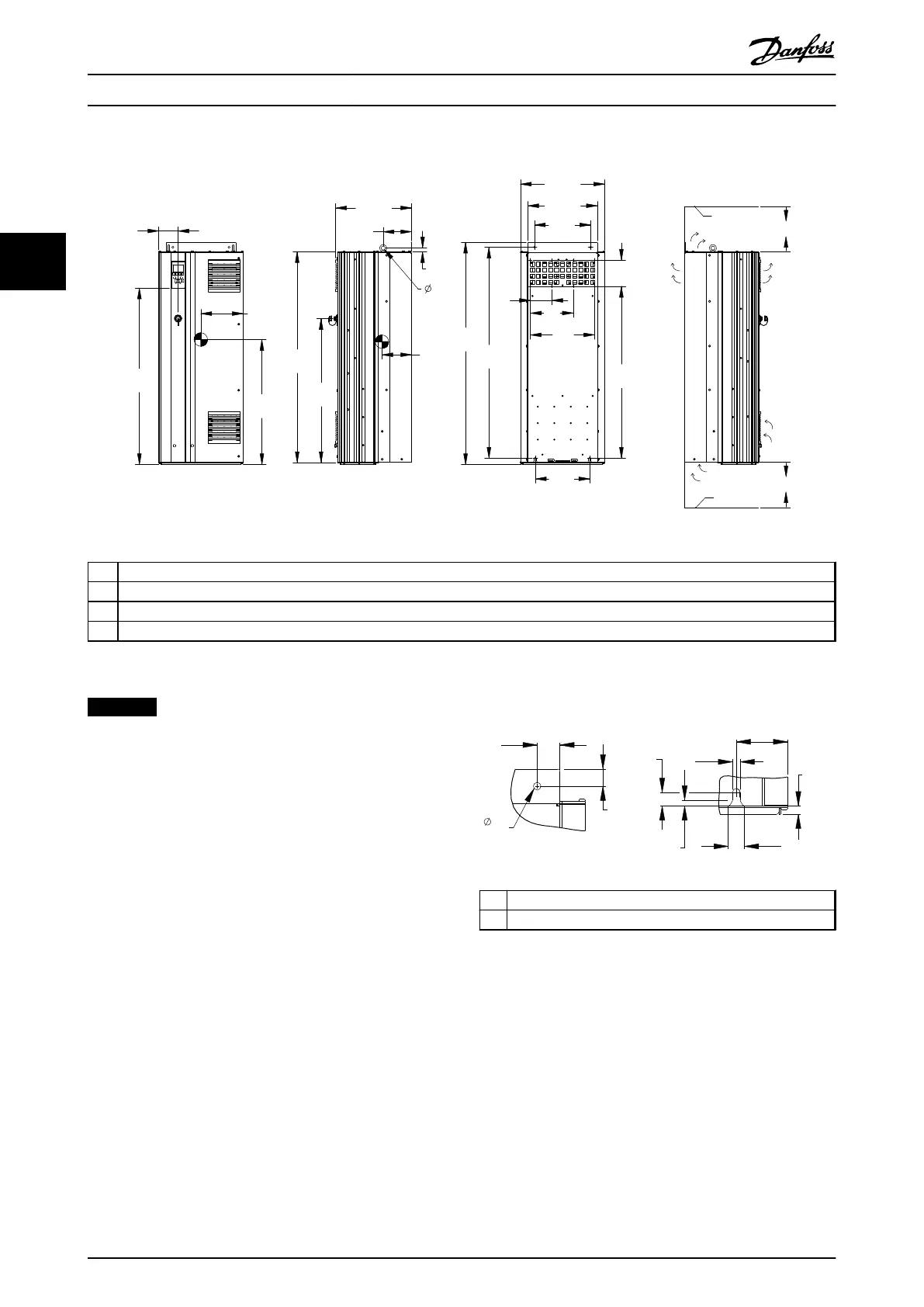
1 Ceiling
2 Air space outlet minimum 225 mm [8.9 in]
3 Air space inlet minimum 225 mm [8.9 in]
4 Floor
Illustration 3.7 Mechanical Dimensions, D2h
NOTICE
If using a kit to direct the airflow from the heat sink to
the outside vent on the back of the frequency converter,
the required ceiling clearance is 100 mm.
1
2
33
[1.3]
25
[1.0]
24
[0.9]
20
[0.8]
75
[2.9]
11
[0.4]
9
[0.3]
11
[0.4]
12
[0.5]
130BD515.10
1 Top mounting hole detail
2 Bottom mounting slot detail
Illustration 3.8 Detail Dimensions, D2h
Installation Operating Instructions
16 Danfoss A/S © Rev. 05/2014 All rights reserved. MG16J202
33
 Loading...


