Troubleshooting
•
Check fan resistance.
•
Check soft charge fuses.
WARNING 24, External fan fault
The fan warning function is an extra protective function
that checks if the fan is running/mounted. The fan warning
can be disabled in 14-53 Fan Monitor ([0] Disabled).
Troubleshooting
•
Check fan resistance.
•
Check soft charge fuses.
ALARM 29, Heat Sink temp
The maximum temperature of the heat sink has been
exceeded. The temperature fault does not reset until the
temperature drops below a defined heat sink temperature.
The trip and reset points are different based on the
frequency converter power size.
Troubleshooting
Check for the following conditions
•
Ambient temperature too high
•
Motor cable too long
•
Incorrect airflow clearance above and below the
frequency converter
•
Blocked airflow around the frequency converter
•
Damaged heat sink fan
•
Dirty heat sink
This alarm is based on the temperature measured by the
heat sink sensor mounted inside the IGBT modules.
Troubleshooting
•
Check fan resistance.
•
Check soft charge fuses.
•
Check IGBT thermal sensor.
ALARM 30, Motor phase U missing
Motor phase U between the frequency converter and the
motor is missing.
Troubleshooting
•
Remove power from the frequency converter and
check motor phase U.
ALARM 31, Motor phase V missing
Motor phase V between the frequency converter and the
motor is missing.
Troubleshooting
•
Remove power from the frequency converter and
check motor phase V.
ALARM 32, Motor phase W missing
Motor phase W between the frequency converter and the
motor is missing.
Troubleshooting
•
Remove power from the frequency converter and
check motor phase W.
ALARM 33, Inrush fault
Too many power-ups have occurred within a short time
period.
Troubleshooting
•
Let the unit cool to operating temperature.
WARNING/ALARM 34, Fieldbus communication fault
The fieldbus on the communication option card is not
working.
WARNING/ALARM 35, Option fault
Option fault. Please contact your supplier.
WARNING/ALARM 36, Mains failure
This warning/alarm is only active if the supply voltage to
the frequency converter is lost and 14-10 Mains Failure is
NOT set to [0] No Function.
Troubleshooting
•
Check the fuses to the frequency converter and
mains power supply to the unit.
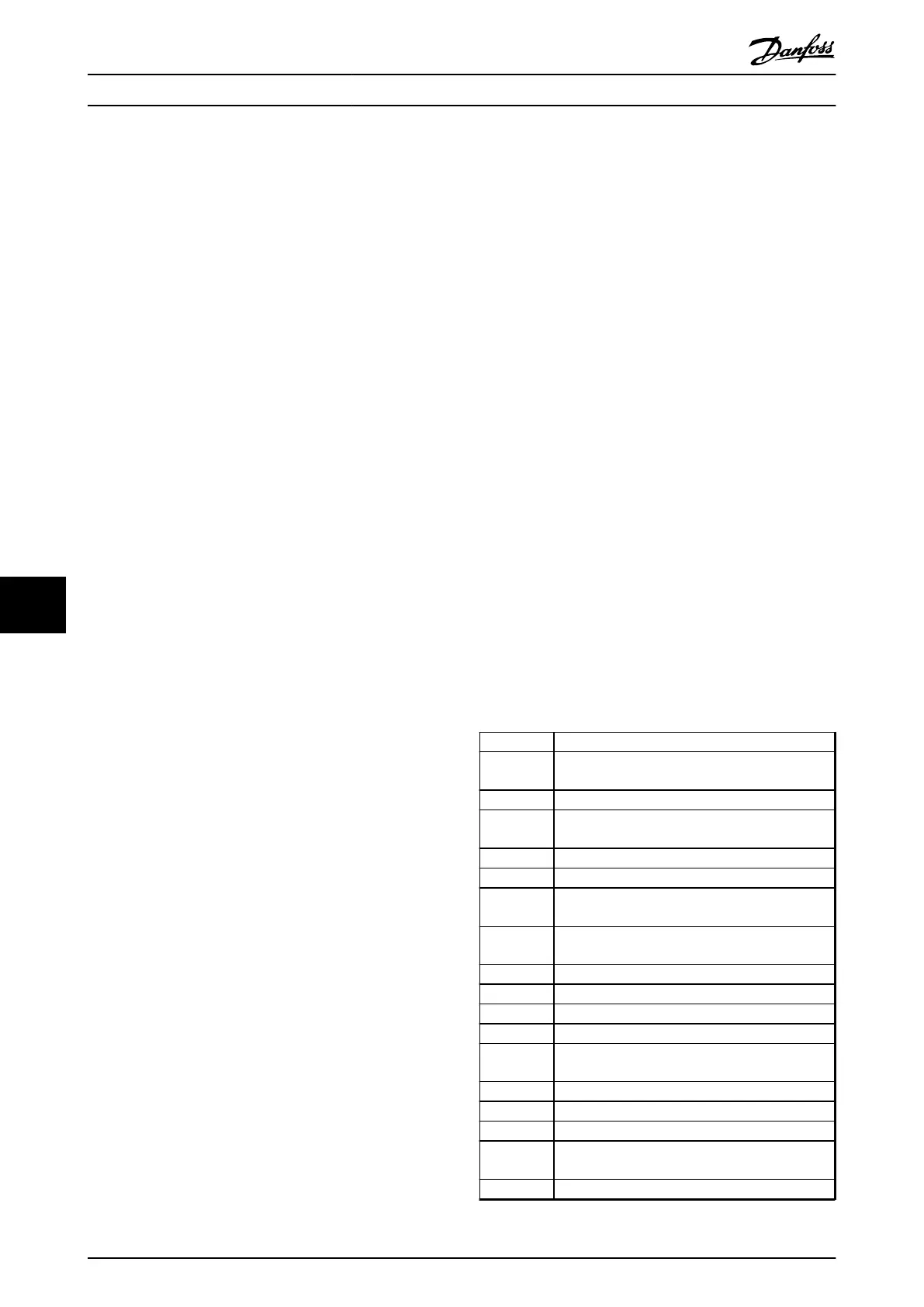
ALARM 38, Internal fault
When an internal fault occurs, a code number defined in
Table 9.2 is displayed.
Troubleshooting
•
Cycle power.
•
Check that the option is properly installed.
•
Check for loose or missing wiring.
It may be necessary to contact the Danfoss supplier or
service department. Note the code number for further
troubleshooting directions.
No. Text
0 Serial port cannot be initialised. Contact the
Danfoss supplier or Danfoss Service Department.
256-258 Power EEPROM data is defective or too old.
512 Control board EEPROM data is defective or too
old.
513 Communication time out reading EEPROM data
514 Communication time out reading EEPROM data
515 Application oriented control cannot recognize the
EEPROM data.
516 Cannot write to the EEPROM because a write
command is on progress.
517 Write command is under time-out.
518 Failure in the EEPROM
519 Missing or invalid barcode data in EEPROM
783 Parameter value outside of min/max limits
1024-1279 A CAN telegram that has to be sent can not be
sent.
1281 Digital signal processor flash time-out
1282 Power micro software version mismatch
1283 Power EEPROM data version mismatch
1284 Cannot read digital signal processor software
version.
1299 Option SW in slot A is too old.
Warnings and Alarms Operating Instructions
88 Danfoss A/S © Rev. 05/2014 All rights reserved. MG16J202
99

 Loading...


