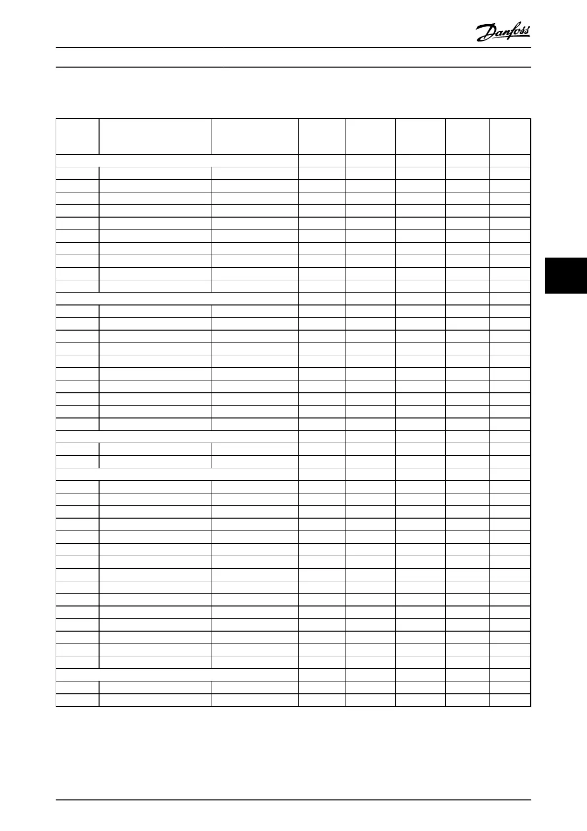
6.3.23 34-** MCO Data Readouts
Par. No. # Parameter description Default value 4-set-up FC 302
only
Change
during
operation
Conver-
sion index
Type
34-0* PCD Write Par.
34-01 PCD 1 write to MCO 0 N/A All set-ups TRUE 0 Uint16
34-02 PCD 2 write to MCO 0 N/A All set-ups TRUE 0 Uint16
34-03 PCD 3 write to MCO 0 N/A All set-ups TRUE 0 Uint16
34-04 PCD 4 write to MCO 0 N/A All set-ups TRUE 0 Uint16
34-05 PCD 5 write to MCO 0 N/A All set-ups TRUE 0 Uint16
34-06 PCD 6 write to MCO 0 N/A All set-ups TRUE 0 Uint16
34-07 PCD 7 write to MCO 0 N/A All set-ups TRUE 0 Uint16
34-08 PCD 8 write to MCO 0 N/A All set-ups TRUE 0 Uint16
34-09 PCD 9 write to MCO 0 N/A All set-ups TRUE 0 Uint16
34-10 PCD 10 write to MCO 0 N/A All set-ups TRUE 0 Uint16
34-2* PCD Read Par.
34-21 PCD 1 read from MCO 0 N/A All set-ups TRUE 0 Uint16
34-22 PCD 2 read from MCO 0 N/A All set-ups TRUE 0 Uint16
34-23 PCD 3 read from MCO 0 N/A All set-ups TRUE 0 Uint16
34-24 PCD 4 read from MCO 0 N/A All set-ups TRUE 0 Uint16
34-25 PCD 5 read from MCO 0 N/A All set-ups TRUE 0 Uint16
34-26 PCD 6 read from MCO 0 N/A All set-ups TRUE 0 Uint16
34-27 PCD 7 read from MCO 0 N/A All set-ups TRUE 0 Uint16
34-28 PCD 8 read from MCO 0 N/A All set-ups TRUE 0 Uint16
34-29 PCD 9 read from MCO 0 N/A All set-ups TRUE 0 Uint16
34-30 PCD 10 read from MCO 0 N/A All set-ups TRUE 0 Uint16
34-4* Inputs & Outputs
34-40 Digital inputs 0 N/A All set-ups TRUE 0 Uint16
34-41 Digital outputs 0 N/A All set-ups TRUE 0 Uint16
34-5* Process Data
34-50 Actual position 0 N/A All set-ups TRUE 0 Int32
34-51 Commanded position 0 N/A All set-ups TRUE 0 Int32
34-52 Actual Master position 0 N/A All set-ups TRUE 0 Int32
34-53 Slave Index position 0 N/A All set-ups TRUE 0 Int32
34-54 Master index position 0 N/A All set-ups TRUE 0 Int32
34-55 Curve position 0 N/A All set-ups TRUE 0 Int32
34-56 Track error 0 N/A All set-ups TRUE 0 Int32
34-57 Synchronizing error 0 N/A All set-ups TRUE 0 Int32
34-58 Actual velocity 0 N/A All set-ups TRUE 0 Int32
34-59 Actual master velocity 0 N/A All set-ups TRUE 0 Int32
34-60 Synchronizing status 0 N/A All set-ups TRUE 0 Int32
34-61 Axis status 0 N/A All set-ups TRUE 0 Int32
34-62 Program status 0 N/A All set-ups TRUE 0 Int32
34-64 MCO 302 status 0 N/A All set-ups TRUE 0 Uint16
34-65 MCO 302 control 0 N/A All set-ups TRUE 0 Uint16
34-7* Diagnosis readouts
34-70 MCO alarm word 1 0 N/A All set-ups FALSE 0 Uint32
34-71 MCO alarm word 2 0 N/A All set-ups FALSE 0 Uint32
Programming Operating Instructions
MG37A202 Danfoss A/S © Rev. 2014-07-29 All rights reserved. 105
6 6

 Loading...


