Number Text
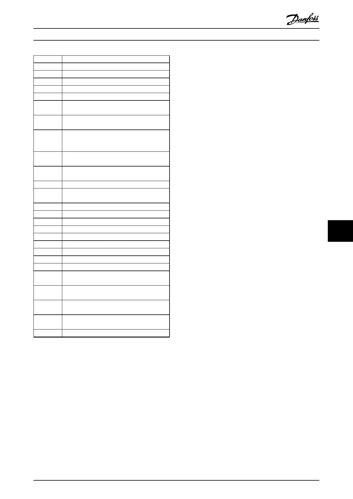
2304 Could not read any data from the power EEPROM.
2305 Missing software version from the power unit.
2314 Missing power unit data from the power unit.
2315 Missing software version from the power unit.
2316 Missing lo_statepage from the power unit.
2324 The power card configuration is determined to be
incorrect at power-up.
2325 A power card has stopped communicating while
mains power is applied.
2326 The power card configuration is determined to be
incorrect after the delay for power cards to
register.
2327 Too many power card locations have been
registered as present.
2330 The power size information between the power
cards does not match.
2561 No communication from DSP to ATACD.
2562 No communication from ATACD to DSP (state
running).
2816 Stack overflow control board module
2817 Scheduler slow tasks
2818 Fast tasks
2819 Parameter thread
2820 LCP stack overflow
2821 Serial port overflow
2822 USB port overflow
2836 cfListMempool is too small.
3072–5122 The parameter value is outside its limits.
5123 Option in slot A: Hardware incompatible with the
control board hardware.
5124 Option in slot B: Hardware incompatible with the
control board hardware.
5125 Option in slot C0: Hardware incompatible with the
control board hardware.
5126 Option in slot C1: Hardware incompatible with the
control board hardware.
5376–6231 Out of memory
Table 9.2 Internal Fault, Code Numbers
ALARM 39, Heat sink sensor
No feedback from the heat sink temperature sensor.
The signal from the IGBT thermal sensor is not available on
the power card. The problem could be on the power card,
on the gate drive card, or the ribbon cable between the
power card and gate drive card.
WARNING 40, Overload of digital output terminal 27
Check the load connected to terminal 27 or remove the
short-circuit connection. Check 5-00 Digital I/O Mode and
5-01 Terminal 27 Mode.
WARNING 41, Overload of digital output terminal 29
Check the load connected to terminal 29 or remove the
short-circuit connection. Check 5-00 Digital I/O Mode and
5-02 Terminal 29 Mode.
WARNING 42, Overload of digital output on X30/6 or
overload of digital output on X30/7
For X30/6, check the load connected to X30/6 or remove
the short-circuit connection. Check 5-32 Term X30/6 Digi
Out (MCB 101).
For X30/7, check the load connected to X30/7 or remove
the short-circuit connection. Check 5-33 Term X30/7 Digi
Out (MCB 101).
ALARM 45, Earth fault 2
Ground fault.
Troubleshooting
•
Check for proper grounding and loose
connections.
•
Check for proper wire size.
•
Check the motor cables for short circuits or
leakage currents.
ALARM 46, Power card supply
The supply on the power card is out of range.
There are 3 power supplies generated by the switch mode
power supply (SMPS) on the power card: 24 V, 5 V, and±18
V. When powered with 24 V DC with the MCB 107 option,
only the 24 V and 5 V supplies are monitored. When
powered with 3-phase mains voltage, all 3 supplies are
monitored.
WARNING 47, 24 V supply low
The 24 V DC is measured on the control card. This alarm
appears when the detected voltage of terminal 12 is <18
V.
Troubleshooting
•
Check for a defective control card.
WARNING 48, 1.8 V supply low
The 1.8 V DC supply used on the control card is outside of
the allowable limits. The power supply is measured on the
control card. Check for a defective control card. If an
option card is present, check for overvoltage.
WARNING 49, Speed limit
When the speed is outside of the specified range in
4-11 Motor Speed Low Limit [RPM] and 4-13 Motor Speed
High Limit [RPM], the frequency converter shows a warning.
When the speed is below the specified limit in 1-86 Trip
Speed Low [RPM] (except when starting or stopping), the
frequency converter trips.
ALARM 50, AMA calibration failed
Contact the Danfoss supplier or Danfoss Service.
ALARM 51, AMA check U
nom
and I
nom
The settings for motor voltage, motor current and motor
power are wrong. Check the settings in parameters 1-20 to
1-25.
ALARM 52, AMA low I
nom
The motor current is too low. Check the settings in
4-18 Current Limit.
Warnings and Alarms
Operating Instructions
MG37A202 Danfoss A/S © Rev. 2014-07-29 All rights reserved. 127
9 9

 Loading...


