For D, E, and F enclosures, this alarm is based on the
temperature measured by the heat sink sensor mounted
inside the IGBT modules. For the F enclosures, the thermal
sensor in the rectifier module can also cause this alarm.
Troubleshooting
•
Check the fan resistance.
•
Check the soft charge fuses.
•
Check the IGBT thermal sensor.
ALARM 30, Motor phase U missing
Motor phase U between the frequency converter and the
motor is missing.
Troubleshooting
•
Remove the power from the frequency converter
and check motor phase U.
ALARM 31, Motor phase V missing
Motor phase V between the frequency converter and the
motor is missing.
Troubleshooting
•
Remove the power from the frequency converter
and check motor phase V.
ALARM 32, Motor phase W missing
Motor phase W between the frequency converter and the
motor is missing.
Troubleshooting
•
Remove the power from the frequency converter
and check motor phase W.
ALARM 33, Inrush fault
Too many power-ups have occurred within a short time
period.
Troubleshooting
•
Let the unit cool to operating temperature.
WARNING/ALARM 34, Fieldbus communication fault
The fieldbus on the communication option card is not
working.
WARNING/ALARM 36, Mains failure
This warning/alarm is only active if the supply voltage to
the frequency converter is lost and 14-10 Mains Failure is
not set to option [0] No Function. Check the fuses to the
frequency converter and mains supply to the unit.
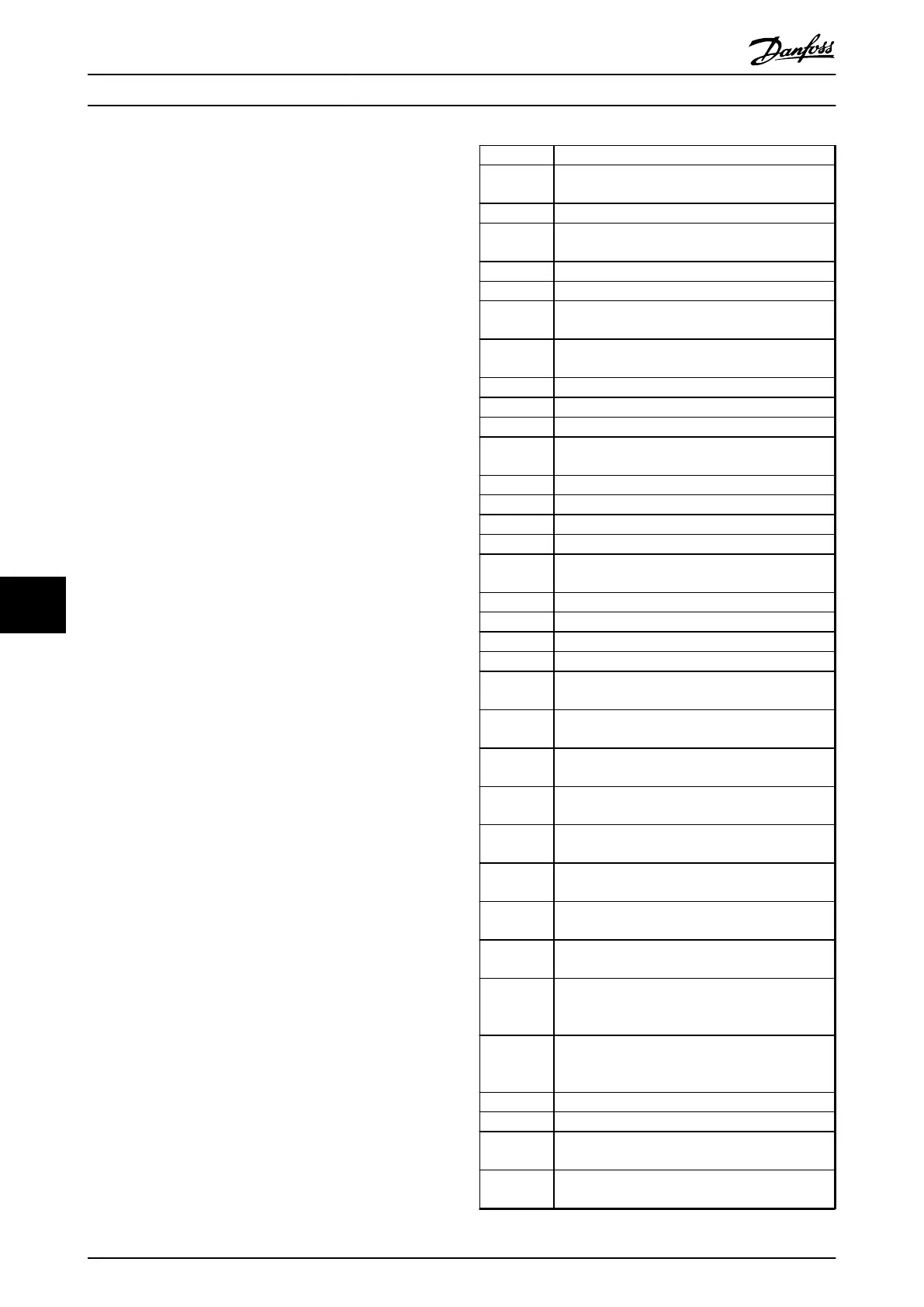
ALARM 38, Internal fault
When an internal fault occurs, a code number defined in
Table 9.2 is displayed.
Troubleshooting
•
Cycle the power.
•
Check that the option is properly installed.
•
Check for loose or missing wiring.
It may be necessary to contact Danfoss Service or the
supplier. Note the code number for further trouble-
shooting directions.
Number Text
0 The serial port cannot be initialised. Contact your
Danfoss supplier or Danfoss Service.
256–258 The power EEPROM data is defective or too old.
512 The control board EEPROM data is defective or too
old.
513 Communication time-out reading EEPROM data
514 Communication time-out reading EEPROM data
515 Application-oriented control cannot recognise the
EEPROM data.
516 Cannot write to the EEPROM because a write
command is in progress.
517 The write command is under time-out.
518 Failure in the EEPROM.
519 Missing or invalid barcode data in EEPROM.
783 Parameter value outside of minimum/maximum
limits.
1024–1279 A CAN telegram could not be sent.
1281 Digital signal processor flash time-out.
1282 Power micro software version mismatch.
1283 Power EEPROM data version mismatch.
1284 Cannot read digital signal processor software
version.
1299 The option software in slot A is too old.
1300 The option software in slot B is too old.
1301 The option software in slot C0 is too old.
1302 The option software in slot C1 is too old.
1315 The option software in slot A is not supported (not
allowed).
1316 The option software in slot B is not supported (not
allowed).
1317 The option software in slot C0 is not supported
(not allowed).
1318 The option software in slot C1 is not supported
(not allowed).
1379 Option A did not respond when calculating the
platform version
1380 Option B did not respond when calculating the
platform version.
1381 Option C0 did not respond when calculating the
platform version.
1382 Option C1 did not respond when calculating the
platform version.
1536 An exception in the application-oriented control is
registered. The debug information is written on
the LCP.
1792 DSP Watch Dog is active. Debugging of power
part data, motor-oriented control data not
transferred correctly.
2049 Power data restarted.
2064–2072 H081x: Option in slot x has restarted.
2080–2088 H082x: Option in slot x has issued a power-up
wait.
2096–2104 H983x: Option in slot x has issued a legal power-
up wait.
Warnings and Alarms Operating Instructions
126 Danfoss A/S © Rev. 2014-07-29 All rights reserved. MG37A202
99

 Loading...


