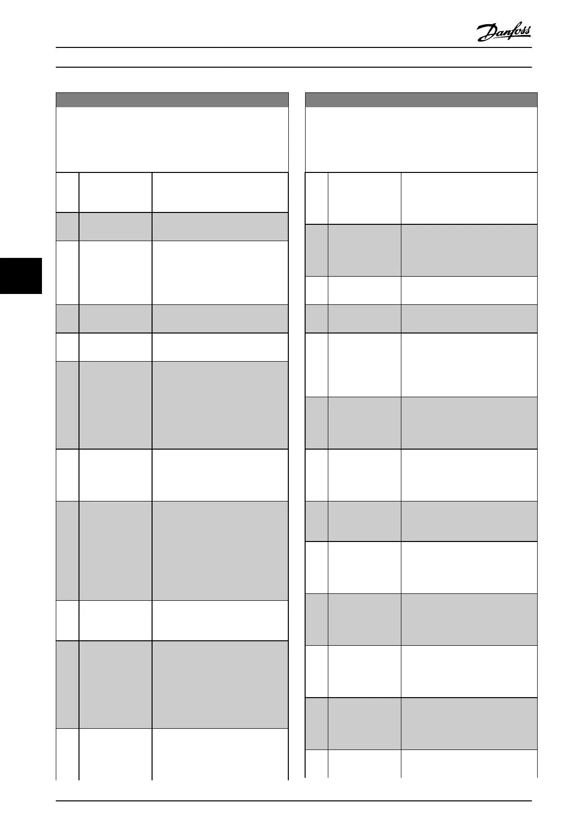
5-40 Function Relay
Array [9]
(Relay 1 [0], Relay 2 [1], Relay 3 [2] (MCB 113), Relay 4 [3] (MCB
113), Relay 5 [4] (MCB 113), Relay 6 [5] (MCB 113), Relay 7 [6]
(MCB 105), Relay 8 [7] (MCB 105), Relay 9 [8] (MCB 105))
Option: Function:
of the motor. If the motor is not
rotating, the output follows the
reference.
[26] Bus OK Active communication (no time-out)
via the serial communication port.
[27] Torque limit & stop Use in performing a coasted stop and
frequency converter in torque limit
condition. If the frequency converter
has received a stop signal and is in
torque limit, the signal is Logic ‘0.’
[28] Brake, no brake
war
Brake is active and there are no
warnings.
[29] Brake ready, no
fault
Brake is ready for operation and there
are no faults.
[30] Brake fault (IGBT) Output is Logic ‘1’ when the brake
IGBT is short-circuited. Use this
function to protect the frequency
converter if there is a fault on the
brake module. Use the digital output/
relay to cut out the main voltage
from the frequency converter.
[31] Relay 123 Digital output/relay is activated when
Control Word [0] is selected in
parameter group 8-** Communication
and Options..
[32] Mech brake ctrl Selection of mechanical brake control.
When selected parameters in
parameter group 2-2* Mechanical
Brake are active. The output must be
reinforced to carry the current for the
coil in the brake. Solved by
connecting an external relay to the
selected digital output.
[33] Safe stop active (FC 302 only) Indicates that the safe
stop on terminal 37 has been
activated.
[36] Control word bit
11
Activate relay 1 via control word from
fieldbus. No other functional impact
in the frequency converter. Typical
application: Controlling auxiliary
devices from fieldbus. The function is
valid when [0] FC profile in
8-10 Control Word Profile is selected.
[37] Control word bit
12
Activate relay 2 (FC 302 only) by
control word from fieldbus. No other
functional impact in the frequency
converter. Typical application:
5-40 Function Relay
Array [9]
(Relay 1 [0], Relay 2 [1], Relay 3 [2] (MCB 113), Relay 4 [3] (MCB
113), Relay 5 [4] (MCB 113), Relay 6 [5] (MCB 113), Relay 7 [6]
(MCB 105), Relay 8 [7] (MCB 105), Relay 9 [8] (MCB 105))
Option: Function:
controlling auxiliary device from
fieldbus. The function is valid when
[0] FC profile in 8-10 Control Word
Profile is selected.
[40] Out of ref range Active when the actual speed is
outside settings in 4-52 Warning
Speed Low to 4-55 Warning Reference
High.
[41] Below reference,
low
Active when actual speed is below
speed reference setting.
[42] Above ref, high Active when actual speed is above
speed reference setting.
[45] Bus ctrl. Controls digital output/relay via bus.
The state of the output is set in
5-90 Digital & Relay Bus Control. The
output state is retained in the event
of bus time-out.
[46] Bus ctrl, 1 if
timeout
Controls output via bus. The state of
the output is set in 5-90 Digital &
Relay Bus Control. If bus time-out, the
output state is set high (On).
[47] Bus ctrl, 0 if
timeout
Controls output via bus. The state of
the output is set in 5-90 Digital &
Relay Bus Control. If bus time-out the
output state is set to low (Off).
[51] MCO controlled Active when an MCO 302 or MCO
305 is connected. The output is
controlled from an option.
[60] Comparator 0
See parameter group 13-1* Smart
Logic Control. If Comparator 0 in SLC
is true, the output goes high.
Otherwise, it is low.
[61] Comparator 1
See parameter group 13-1* Smart
Logic Control. If Comparator 1 in SLC
is true, the output goes high.
Otherwise, it is low.
[62] Comparator 2
See parameter group 13-1* Smart
Logic Control. If Comparator 2 in SLC
is true, the output goes high.
Otherwise, it is low.
[63] Comparator 3
See parameter group 13-1* Smart
Logic Control. If Comparator 3 in SLC
is true, the output goes high.
Otherwise, it is low.
[64] Comparator 4
See parameter group 13-1* Smart
Logic Control. If Comparator 4 in SLC
Programming Operating Instructions
68 Danfoss A/S © Rev. 2014-07-29 All rights reserved. MG37A202
66

 Loading...


