5-40 Function Relay
Array [9]
(Relay 1 [0], Relay 2 [1], Relay 3 [2] (MCB 113), Relay 4 [3] (MCB
113), Relay 5 [4] (MCB 113), Relay 6 [5] (MCB 113), Relay 7 [6]
(MCB 105), Relay 8 [7] (MCB 105), Relay 9 [8] (MCB 105))
Option: Function:
is true, the output goes high.
Otherwise, it is low.
[65] Comparator 5
See parameter group 13-1* Smart
Logic Control. If Comparator 5 in SLC
is true, the output goes high.
Otherwise, it is low.
[70] Logic rule 0
See parameter group 13-4* Logic
Rules. If Logic Rule 0 in SLC is true,
the output goes high. Otherwise, it is
low.
[71] Logic rule 1
See parameter group 13-4* Logic
Rules. If Logic Rule 1 in SLC is true,
the output goes high. Otherwise, it is
low.
[72] Logic rule 2
See parameter group 13-4* Logic
Rules. If Logic Rule 2 in SLC is true,
the output goes high. Otherwise, it is
low.
[73] Logic rule 3 See parameter group 13-4*(Smart
Logic Control). If Logic Rule 3 in SLC
is true, the output goes high.
Otherwise, it is low.
[74] Logic rule 4
See parameter group 13-4* Logic
Rules. If Logic Rule 4 in SLC is true,
the output goes high. Otherwise, it is
low.
[75] Logic rule 5
See parameter group 13-4* Logic
Rules. If Logic Rule 5 in SLC is true,
the output goes high. Otherwise, it is
low.
[80] SL digital output A
See 13-52 SL Controller Action. Output
A is low on smart logic action [32] Set
digital out A low. Output A is high on
smart logic action [38] Set digital out
A high.
[81] SL digital output B
See 13-52 SL Controller Action. Output
B is low on smart logic action [33] Set
digital out B low. Output B is high on
smart logic action [39] Set digital out
B high.
[82] SL digital output C
See 13-52 SL Controller Action. Output
C is low on smart logic action [34] Set
digital out C low. Output C is high on
smart logic action [40] Set digital out
C high.
5-40 Function Relay
Array [9]
(Relay 1 [0], Relay 2 [1], Relay 3 [2] (MCB 113), Relay 4 [3] (MCB
113), Relay 5 [4] (MCB 113), Relay 6 [5] (MCB 113), Relay 7 [6]
(MCB 105), Relay 8 [7] (MCB 105), Relay 9 [8] (MCB 105))
Option: Function:
[83] SL digital output D
See 13-52 SL Controller Action. Output
D is low on smart logic action [35] Set
digital out D low. Output D is high on
smart logic action [41] Set digital out
D high.
[84] SL digital output E
See 13-52 SL Controller Action. Output
E is low on smart logic action [36] Set
digital out E low. Output E is high on
smart logic action [42] Set digital out E
high.
[85] SL digital output F
See 13-52 SL Controller Action. Output
F is low on smart logic action [37] Set
digital out F low. Output F is high on
smart logic action [43] Set digital out F
high.
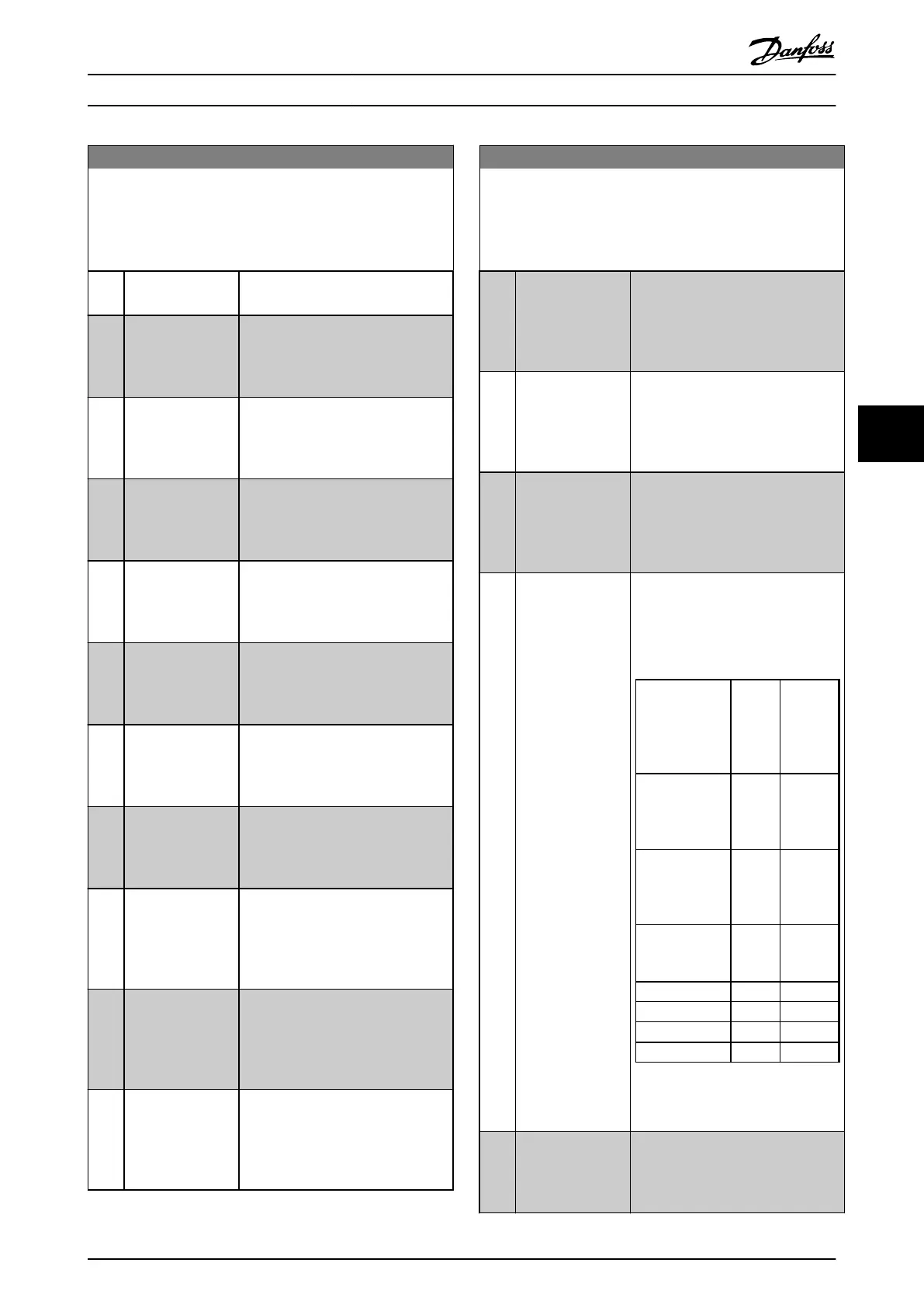
[120] Local ref active
Output is high when 3-13 Reference
Site = [2] Local or when
3-13 Reference Site = [0] Linked to
Hand/Auto at the same time as the
LCP is in [Hand on] mode.
Reference site
set in
3-13 Reference
Site
Local
referen
ce
active
[120]
Remote
reference
active
[121]
Reference site:
Local
3-13 Reference
Site [2]
1 0
Reference site:
Remote
3-13 Reference
Site [1]
0 1
Reference site:
Linked to Hand/
Auto
Hand 1 0
Hand ⇒ off
1 0
Auto ⇒ off
0 0
Auto 0 1
Table 6.9 Local and Remote
Reference
[121]
Remote ref active
Output is high when 3-13 Reference
Site = [1] Remote or [0] Linked to
Hand/Auto while the LCP is in [Auto
on] mode. See Table 6.9.
Programming Operating Instructions
MG37A202 Danfoss A/S © Rev. 2014-07-29 All rights reserved. 69
6 6

 Loading...


