5-40 Function Relay
Array [9]
(Relay 1 [0], Relay 2 [1], Relay 3 [2] (MCB 113), Relay 4 [3] (MCB
113), Relay 5 [4] (MCB 113), Relay 6 [5] (MCB 113), Relay 7 [6]
(MCB 105), Relay 8 [7] (MCB 105), Relay 9 [8] (MCB 105))
Option: Function:
[122] No alarm Output is high when no alarm is
present.
[123] Start command
activ
Output is high when the start
command is high (via digital input,
bus connection or [Hand on] or [Auto
on], and a stop has been the last
command.
[124] Running reverse Output is high when the frequency
converter is running counter
clockwise (the logical product of the
status bits ‘running’ and ‘reverse’).
[125] Drive in hand
mode
Output is high when the frequency
converter is in [Hand on] mode (as
indicated by the LED light above
[Hand on]).
[126] Drive in auto mode Output is high when the frequency
converter is in ‘Auto’ mode (as
indicated by LED on above [Auto
on]).
NOTICE
Set switches S201 (A53) and S202 (A54) as specified in
this section when performing a control card test in
parameter 14-22 Operation Mode. Otherwise, the test
fails.
14-22 Operation Mode
Option: Function:
Use this parameter to specify normal
operation, perform tests, or initialise all
parameters except 15-03 Power Up's,
15-04 Over Temp's and 15-05 Over Volt's. This
function is active only when the power is
cycled to the frequency converter.
Select [0] Normal operation for normal
operation of the frequency converter with
the motor in the selected application.
Select [1] Control card test to test the analog
and digital inputs and outputs and the +10 V
control voltage. The test requires a test
connector with internal connections. To
perform the control card test:
14-22 Operation Mode
Option: Function:
1.
Select [1] Control card test.
2. Disconnect the mains supply and
wait for the light in the display to
go out.
3. Set switches S201 (A53) and S202
(A54) = ‘ON’/I.
4. Insert the test plug.
5. Connect to mains supply.
6. Carry out various tests.
7. The results are displayed on the LCP
and the frequency converter moves
into an infinite loop.
8.
Parameter 14-22 Operation Mode is
automatically set to normal
operation. Perform a power cycle to
start up in normal operation after a
control card test.
If the test is OK
LCP read-out: Control card OK.
Disconnect the mains supply and remove the
test plug. The green LED on the Control Card
lights up.
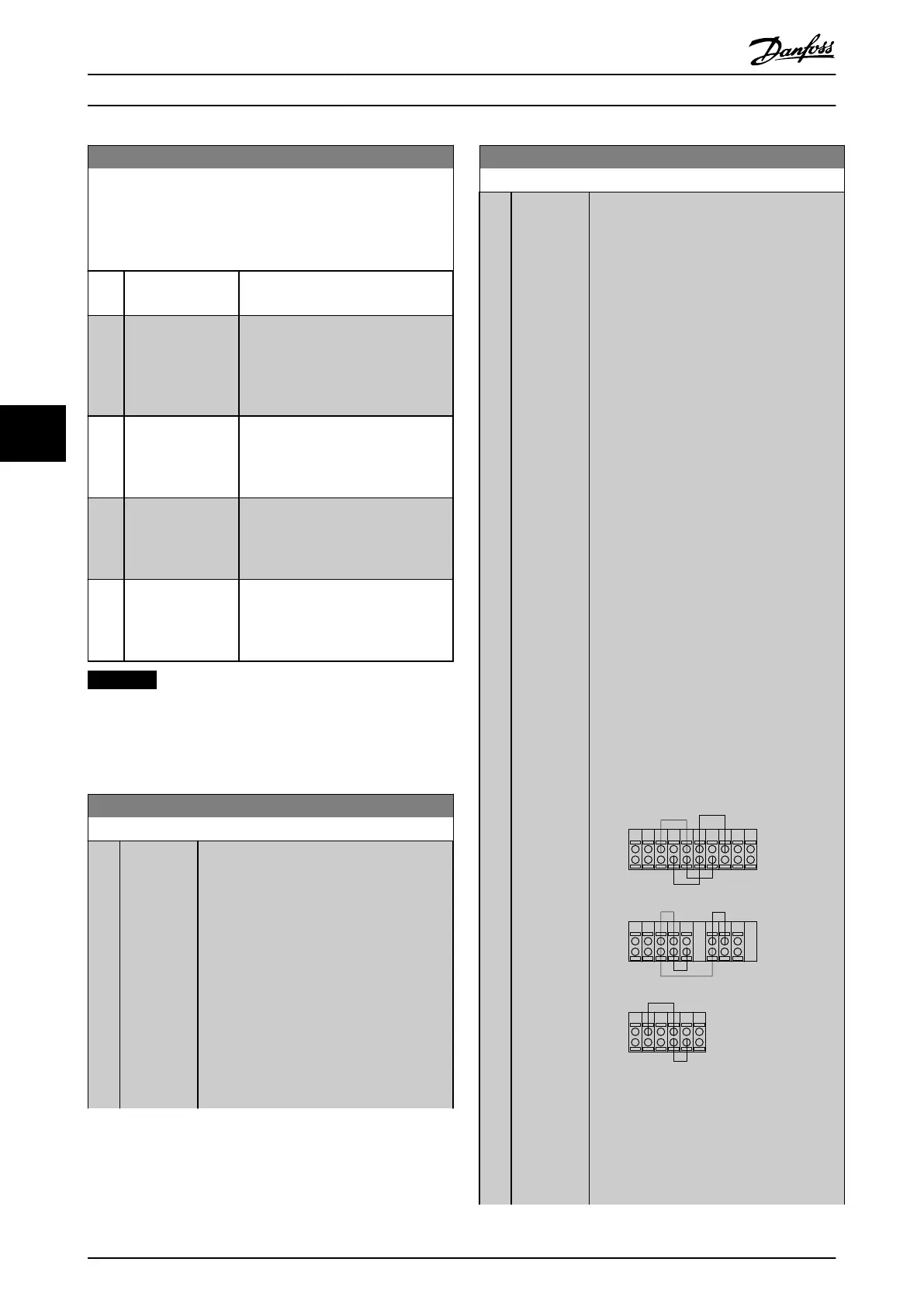
If the test fails
LCP read-out: Control card I/O failure.
Replace the frequency converter or control
card. The red LED on the control card is
turned on. Test plugs (connect the following
terminals to one another): 18 - 27 - 32; 19 -
29 - 33; 42 - 53 - 54
130BA097.12
FC 302
FC 301
FC 301 &
FC 302
1312 18 37322719 29 33 20
5039 42 5453 55
191812 13 203327 32
Illustration 6.13 Control Card Test
Connections
Select [2] Initialisation to reset all parameter
values to default settings, except for
15-03 Power Up's, 15-04 Over Temp's, and
Programming
Operating Instructions
70 Danfoss A/S © Rev. 2014-07-29 All rights reserved. MG37A202
66

 Loading...


