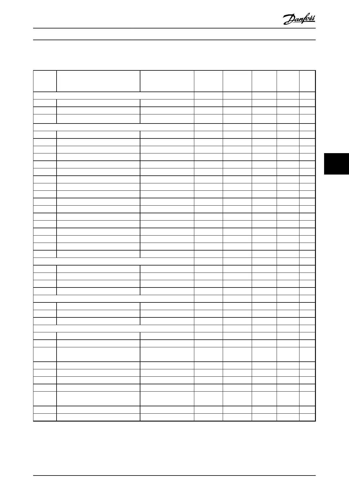
6.3.7 5-** Digital In/Out
Par. No. # Parameter description Default value 4-set-up FC 302
only
Change
during
operation
Conver-
sion
index
Type
5-0* Digital I/O mode
5-00 Digital I/O mode [0] PNP All set-ups FALSE - Uint8
5-01 Terminal 27 mode [0] Input All set-ups TRUE - Uint8
5-02 Terminal 29 mode [0] Input All set-ups x TRUE - Uint8
5-1* Digital Inputs
5-10 Terminal 18 digital input null All set-ups TRUE - Uint8
5-11 Terminal 19 digital input null All set-ups TRUE - Uint8
5-12 Terminal 27 digital input null All set-ups TRUE - Uint8
5-13 Terminal 29 digital input null All set-ups x TRUE - Uint8
5-14 Terminal 32 digital input null All set-ups TRUE - Uint8
5-15 Terminal 33 digital input null All set-ups TRUE - Uint8
5-16 Terminal X30/2 digital input null All set-ups TRUE - Uint8
5-17 Terminal X30/3 digital input null All set-ups TRUE - Uint8
5-18 Terminal X30/4 digital input null All set-ups TRUE - Uint8
5-19 Terminal 37 safe stop [1] Safe Stop Alarm 1 set-up TRUE - Uint8
5-20 Terminal X46/1 digital input [0] No operation All set-ups TRUE - Uint8
5-21 Terminal X46/3 digital input [0] No operation All set-ups TRUE - Uint8
5-22 Terminal X46/5 digital input [0] No operation All set-ups TRUE - Uint8
5-23 Terminal X46/7 digital input [0] No operation All set-ups TRUE - Uint8
5-24 Terminal X46/9 digital input [0] No operation All set-ups TRUE - Uint8
5-25 Terminal X46/11 digital input [0] No operation All set-ups TRUE - Uint8
5-26 Terminal X46/13 digital input [0] No operation All set-ups TRUE - Uint8
5-3* Digital Outputs
5-30 Terminal 27 digital output null All set-ups TRUE - Uint8
5-31 Terminal 29 digital output null All set-ups x TRUE - Uint8
5-32 Term X30/6 digi out (MCB 101) null All set-ups TRUE - Uint8
5-33 Term X30/7 digi out (MCB 101) null All set-ups TRUE - Uint8
5-4* Relays
5-40 Function relay null All set-ups TRUE - Uint8
5-41 On delay, relay 0.01 s All set-ups TRUE -2 Uint16
5-42 Off delay, relay 0.01 s All set-ups TRUE -2 Uint16
5-5* Pulse Input
5-50 Term. 29 low frequency 100 Hz All set-ups x TRUE 0 Uint32
5-51 Term. 29 high frequency 100 Hz All set-ups x TRUE 0 Uint32
5-52 Term. 29 low ref./feedb. value
0.000 ReferenceFeed-
backUnit All set-ups x TRUE -3 Int32
5-53 Term. 29 high ref./feedb. value App.Dependent All set-ups x TRUE -3 Int32
5-54 Pulse filter time constant #29 100 ms All set-ups x FALSE -3 Uint16
5-55 Term. 33 low frequency 100 Hz All set-ups TRUE 0 Uint32
5-56 Term. 33 high frequency 100 Hz All set-ups TRUE 0 Uint32
5-57 Term. 33 low ref./feedb. value
0.000 ReferenceFeed-
backUnit All set-ups TRUE -3 Int32
5-58 Term. 33 high ref./feedb. value App.Dependent All set-ups TRUE -3 Int32
5-59 Pulse filter time constant #33 100 ms All set-ups FALSE -3 Uint16
Programming Operating Instructions
MG37A202 Danfoss A/S © Rev. 2014-07-29 All rights reserved. 81
6 6

 Loading...


