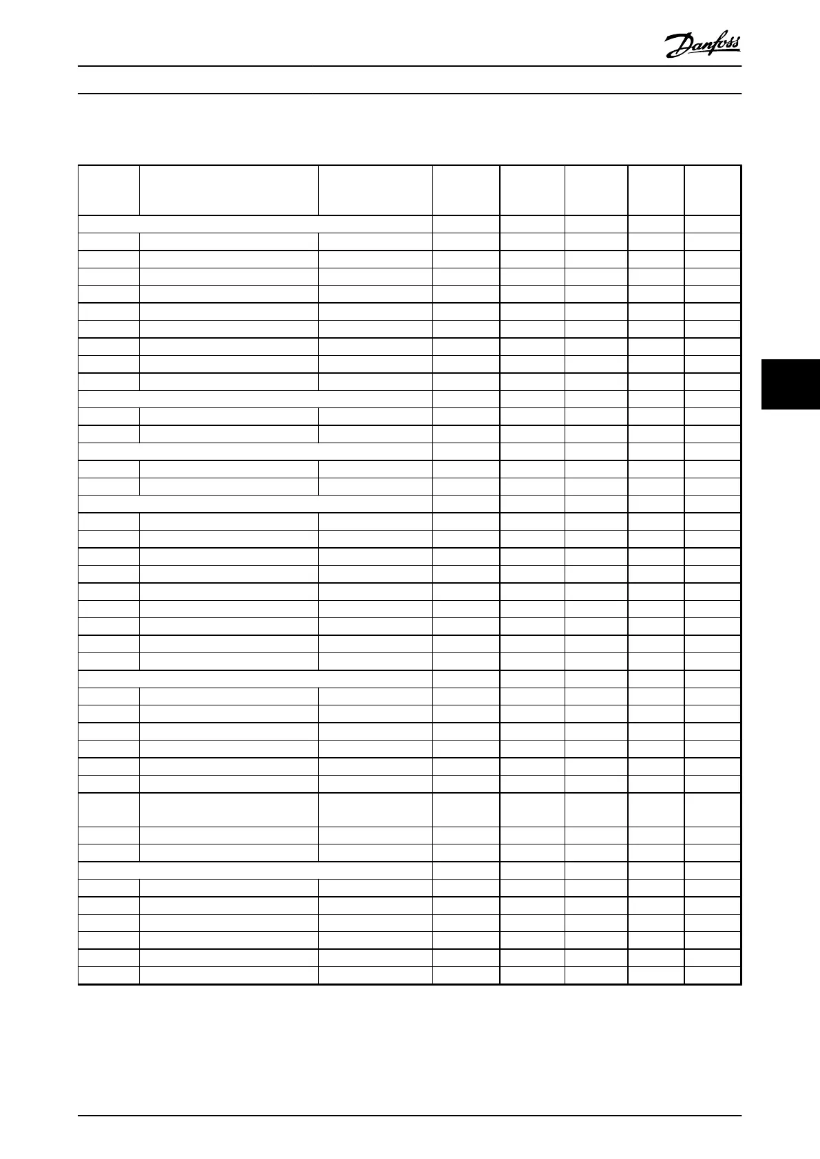
6.3.9 7-** Controllers
Par. No. # Parameter description Default value 4-set-up FC 302
only
Change
during
operation
Conver-
sion
index
Type
7-0* Speed PID Ctrl.
7-00 Speed PID feedback source null All set-ups FALSE - Uint8
7-02 Speed PID proportional gain App.Dependent All set-ups TRUE -3 Uint16
7-03 Speed PID integral time App.Dependent All set-ups TRUE -4 Uint32
7-04 Speed PID differentiation time App.Dependent All set-ups TRUE -4 Uint16
7-05 Speed PID diff. gain limit 5.0 N/A All set-ups TRUE -1 Uint16
7-06 Speed PID lowpass filter time App.Dependent All set-ups TRUE -4 Uint16
7-07 Speed PID feedback gear ratio 1.0000 N/A All set-ups FALSE -4 Uint32
7-08 Speed PID feed forward factor 0 % All set-ups FALSE 0 Uint16
7-09 Speed PID error correction w/ramp 300RPM All set-ups TRUE 67 Uint32
7-1* Torque PI Ctrl.
7-12 Torque PI proportional gain 100 % All set-ups TRUE 0 Uint16
7-13 Torque PI integration time 0.020 s All set-ups TRUE -3 Uint16
7-2* Process Ctrl. Feedb
7-20 Process CL feedback 1 resource [0] No function All set-ups TRUE - Uint8
7-22 Process CL feedback 2 resource [0] No function All set-ups TRUE - Uint8
7-3* Process PID Ctrl.
7-30 Process PID normal/ inverse control [0] Normal All set-ups TRUE - Uint8
7-31 Process PID anti windup [1] On All set-ups TRUE - Uint8
7-32 Process PID start speed 0 RPM All set-ups TRUE 67 Uint16
7-33 Process PID proportional gain 0.01 N/A All set-ups TRUE -2 Uint16
7-34 Process PID integral time 10000.00 s All set-ups TRUE -2 Uint32
7-35 Process PID differentiation time 0.00 s All set-ups TRUE -2 Uint16
7-36 Process PID diff. gain limit 5.0 N/A All set-ups TRUE -1 Uint16
7-38 Process PID feed forward factor 0 % All set-ups TRUE 0 Uint16
7-39 On reference bandwidth 5 % All set-ups TRUE 0 Uint8
7-4* Adv. Process PID I
7-40 Process PID I-part reset [0] No All set-ups TRUE - Uint8
7-41 Process PID output neg. clamp -100 % All set-ups TRUE 0 Int16
7-42 Process PID output pos. clamp 100 % All set-ups TRUE 0 Int16
7-43 Process PID gain scale at min. ref. 100 % All set-ups TRUE 0 Int16
7-44 Process PID gain scale at max. ref. 100 % All set-ups TRUE 0 Int16
7-45 Process PID feed fwd resource [0] No function All set-ups TRUE - Uint8
7-46
Process PID feed fwd normal/inv.
ctrl. [0] Normal All set-ups TRUE - Uint8
7-48 PCD feed forward 0 N/A All set-ups x TRUE 0 Uint16
7-49 Process PID output normal/inv. ctrl. [0] Normal All set-ups TRUE - Uint8
7-5* Adv. Process PID II
7-50 Process PID extended PID [1] Enabled All set-ups TRUE - Uint8
7-51 Process PID feed fwd gain 1.00 N/A All set-ups TRUE -2 Uint16
7-52 Process PID feed fwd ramp up 0.01 s All set-ups TRUE -2 Uint32
7-53 Process PID feed fwd ramp down 0.01 s All set-ups TRUE -2 Uint32
7-56 Process PID ref. filter time 0.001 s All set-ups TRUE -3 Uint16
7-57 Process PID Fb. filter time 0.001 s All set-ups TRUE -3 Uint16
Programming Operating Instructions
MG37A202 Danfoss A/S © Rev. 2014-07-29 All rights reserved. 85
6 6

 Loading...


