The following must be programmed in order shown (see explanation of settings in the VLT
®
AutomationDrive FC 360
Programming Guide)
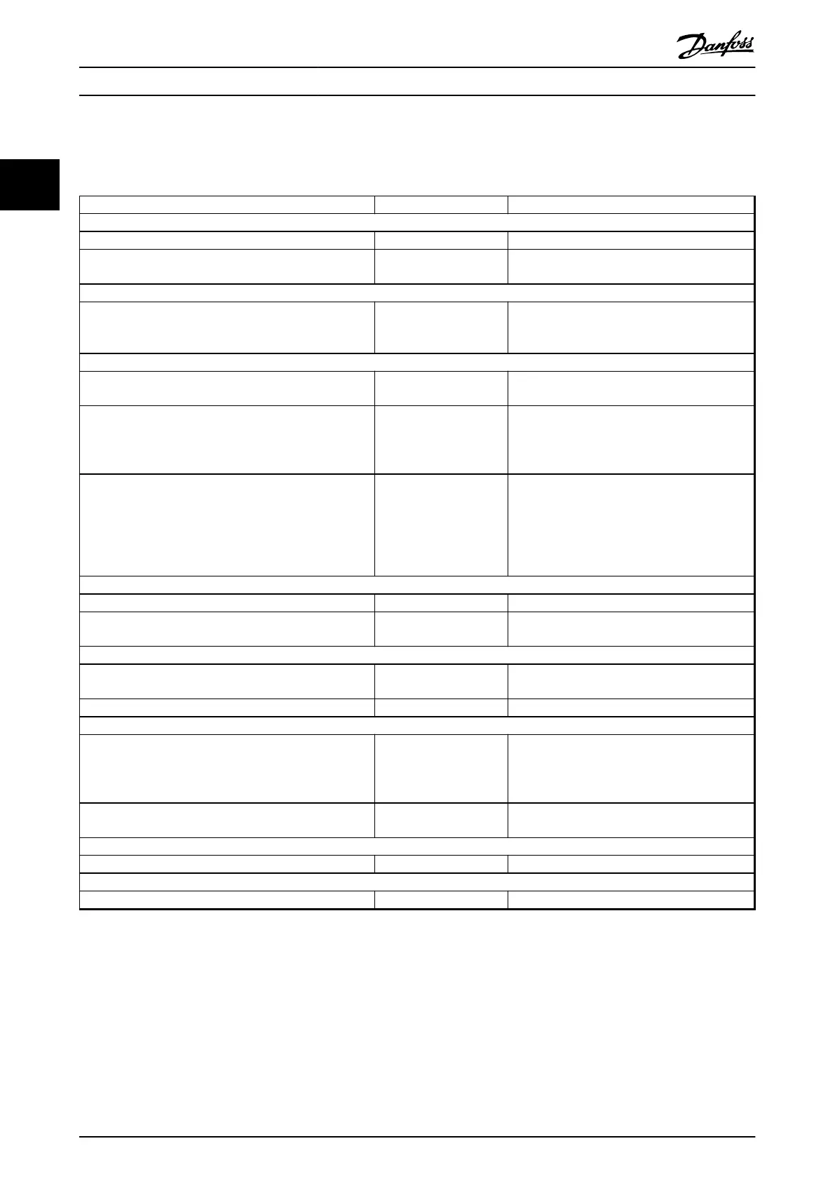
In Table 2.5 it is assumed that all other parameters and switches remain at their default setting.
Function Parameter no. Setting
1) Make sure the motor runs properly. Do the following:
Set the motor parameters using name plate data 1-2* As specified by motor name plate
Have the frequency converter makes an Automatic Motor
Adaptation
1-29 Automatic Motor
Adaptation (AMA)
[1] Enable complete AMA
2) Check the motor is running and the encoder is attached properly. Do the following:
Press [Hand On]. Check that the motor is running and note
in which direction it is turning (henceforth referred to as
the “positive direction”).
Set a positive reference.
3) Make sure the drive limits are set to safe values
Set acceptable limits for the references. 3-02 Minimum Reference
3-03 Maximum Reference
0
50
Check that the ramp settings are within drive capabilities
and allowed application operating specifications.
3-41 Ramp 1 Ramp Up
Time
3-42 Ramp 1 Ramp Down
Time
default setting
default setting
Set acceptable limits for the motor speed and frequency. 4-12 Motor Speed Low
Limit [Hz]
4-14 Motor Speed High
Limit [Hz]
4-19 Max Output
Frequency
0 Hz
50 Hz
60 Hz
4) Configure the Speed Control and select the Motor Control principle
Activation of Speed Control 1-00 Configuration Mode [1] Speed closed loop
Selection of Motor Control Principle 1-01 Motor Control
Principle
[1] VVC
plus
5) Configure and scale the reference to the Speed Control
Set up Analog Input 53 as a reference Source 3-15 Reference Resource
1
Not necessary (default)
Scale Analog Input 53 0 RPM (0 V) to 50 RPM (10 V) 6-1* Not necessary (default)
6) Configure the 24 V HTL encoder signal as feedback for the Motor Control and the Speed Control
Set up digital input 32 and 33 as encoder inputs 5-14 Terminal 32 Digital
Input
5-15 Terminal 33 Digital
Input
[82] Encoder input B
[83] Encoder input A
Choose terminal 32/33 as Speed PID feedback 7-00 Speed PID Feedback
Source
[1] 24 V Encoder
7) Tune the Speed Control PID parameters
Use the tuning guidelines when relevant or tune manually 7-0* See the guidelines below
8) Finished!
Save the parameter setting to the LCP for safe keeping 0-50 LCP Copy [1] All to LCP
Table 2.5 Programming Order for Speed PID Control
Product Overview
VLT
®
AutomationDrive FC 360 Design Guide
26 MG06B202 - VLT
®
is a registered Danfoss trademark
22
 Loading...


