4 Application Examples
4.1 Introduction
The examples in this section are intended as a quick
reference for common functionalities.
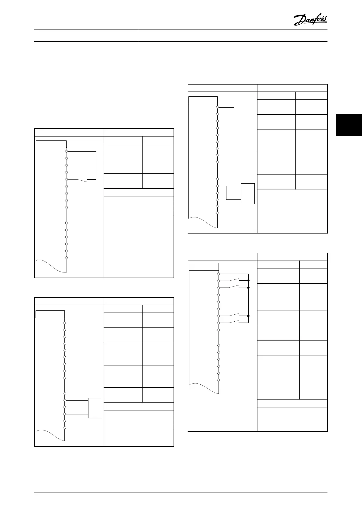
Parameters
FC
+24 V
D IN
D IN
D IN
COM
D IN
D IN
D IN
D IN
+10 V
A IN
A IN
COM
A OUT
12
18
19
20
27
29
32
33
31
50
53
54
55
42
130BD063.11
45
A OUT
Function Setting
1-29 Automatic
Motor
Adaptation
(AMA)
[1] Enable
complete
AMA
5-12 Terminal 27
Digital Input
[2]* Coast
inverse
* = Default Value
Notes/comments: Parameter
group 1-2* Motor Data must be
set according to motor
NOTE
If terminal 12 and 27 are
not connected, set 5-12 to
[0]
Table 4.1 AMA with T27 Connected
Parameters
130BD064.11
+24 V
D IN
D IN
D IN
COM
D IN
D IN
D IN
D IN
+10 V
A IN
A IN
COM
A OUT
12
18
19
20
27
29
32
33
31
50
53
54
55
42
0 ~10 V
+
-
FC
45
A OUT
Function Setting
6-10 Terminal 53
Low Voltage
0.07 V*
6-11 Terminal 53
High Voltage
10 V*
6-14 Terminal 53
Low Ref./Feedb.
Value
0
6-15 Terminal 53
High Ref./Feedb.
Value
1500
6-19 Terminal 53
Mode
[1] Voltage
* = Default Value
Notes/comments:
Table 4.2 Analog Speed Reference (Voltage)
Parameters
130BD065.11
+24 V
D IN
D IN
D IN
COM
D IN
D IN
D IN
D IN
+10 V
A IN
A IN
COM
A OUT
12
18
19
20
27
29
32
33
31
50
53
54
55
42
4 - 20mA
+
-
FC
A OUT
45
Function Setting
6-12 Terminal 53
Low Current
4 mA*
6-13 Terminal 53
High Current
20 mA*
6-14 Terminal 53
Low Ref./Feedb.
Value
0
6-15 Terminal 53
High Ref./Feedb.
Value
1500
6-19 Terminal 53
Mode
[0] current
* = Default Value
Notes/comments:
Table 4.3 Analog Speed Reference (Current)
Parameters
130BD066.11
FC
+24 V
D IN
D IN
D IN
COM
D IN
D IN
D IN
D IN
+10 V
A IN
A IN
COM
A OUT
12
18
19
20
27
29
32
33
31
50
53
54
55
42
45
A OUT
Function Setting
5-10 Terminal 18
Digital Input
[8] Start
5-11 Terminal 19
Digital Input
[10]
Reversing*
5-12 Terminal 27
Digital Input
[0] No
operation
5-14 Terminal 32
Digital Input
[16] Preset
ref bit 0
5-15 Terminal 33
Digital Input
[17] Preset
ref bit 1
3-10 Preset
Reference
Preset ref. 0
Preset ref. 1
Preset ref. 2
Preset ref. 3
25%
50%
75%
100%
* = Default Value
Notes/comments:
Table 4.4 Start/Stop with Reversing and 4 Preset Speeds
Application Examples
VLT
®
AutomationDrive FC 360 Design Guide
MG06B202 - VLT
®
is a registered Danfoss trademark 59
4 4
 Loading...


