EasyManua.ls Logo

Danfoss VLT FC 360 User Manual

Danfoss VLT FC 360
82 pages
To Next Page IconTo Next Page
To Previous Page IconTo Previous Page
Page #41 background imageLoading...
Page #41 background image
NOTE
OVC can be activated when running a PM motor (when
1-10 Motor Construction is set to [1] PM non salient SPM).
2.10 Smart Logic Controller
Smart Logic Control (SLC) is essentially a sequence of user
defined actions (see 13-52 SL Controller Action [x]) executed
by the SLC when the associated user defined event (see
13-51 SL Controller Event [x]) is evaluated as TRUE by the
SLC.
The condition for an event can be a particular status or
that the output from a Logic Rule or a Comparator
Operand becomes TRUE. That will lead to an associated
action as illustrated:
. . .
. . .
Par. 13-43
Comparator Operator
Par. 13-43
Logic Rule Operator 2
Par. 13-51
SL Controller Event
Par. 13-51
SL Controller Action
130BB671.10
Coast
Start timer
Set Do X low
Select set-up 2
. . .
Running
Warning
Torque limit
Digital inpute X 30/2
. . .
=
TRUE longer than..
. . .
. . .
Illustration 2.24 Associated Action
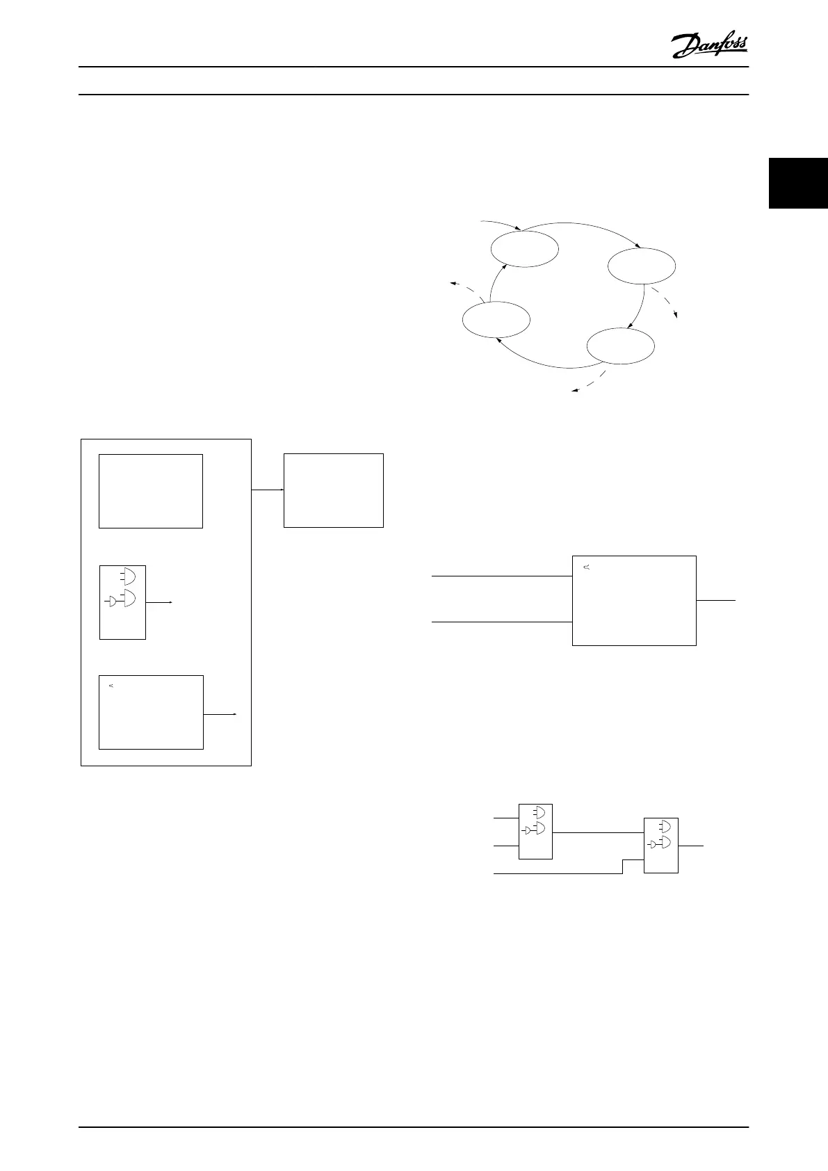
Events and actions are each numbered and linked together
in pairs (states). This means that when event [0] is fulfilled
(attains the value TRUE), action [0] is executed. After this,
the conditions of event [1] will be evaluated and if
evaluated TRUE, action [1] will be executed and so on.
Only one event will be evaluated at any time. If an event is
evaluated as FALSE, nothing happens (in the SLC) during
the current scan interval and no other events will be
evaluated. This means that when the SLC starts, it
evaluates event [0] (and only event [0]) each scan interval.
Only when event [0] is evaluated TRUE, will the SLC
execute action [0] and start evaluating event [1]. It is
possible to programme from 1 to 20 events and actions.
When the last
event/action has been executed, the
sequence starts over again from event [0]/action [0].
Illustration 2.25 shows an example with three event/actions:
130BA062.13
State 1
Event 1/
Action 1
State 2
Event 2/
Action 2
Start
event P13-01
State 3
Event 3/
Action 3
State 4
Event 4/
Action 4
Stop
event P13-02
Stop
event P13-02
Stop
event P13-02
Illustration 2.25 Sequence with Three Event/Actions
Comparators
Comparators are used for comparing continuous variables
(i.e. output frequency, output current, analog input etc.) to
fixed preset values.
Par. 13-11
Comparator Operator
=
TRUE longer than.
. . .
. . .
Par. 13-10
Comparator Operand
Par. 13-12
Comparator Value
130BB672.10
Illustration 2.26 Comparators
Logic Rules
Combine up to three boolean inputs (TRUE/FALSE inputs)
from timers, comparators, digital inputs, status bits and
events using the logical operators AND, OR, and NOT.
. . .
. . .
. . .
. . .
Par. 13-43
Logic Rule Operator 2
Par. 13-41
Logic Rule Operator 1
Par. 13-40
Logic Rule Boolean 1
Par. 13-42
Logic Rule Boolean 2
Par. 13-44
Logic Rule Boolean 3
130BB673.10
Illustration 2.27 Logic Rules
2.11 Extreme Running Conditions
Short circuit (motor phase phase)
The frequency converter is protected against short circuits
by means of current measurement in each of the three
motor phases or in the DC link. A short circuit between
two output phases will cause an overcurrent in the
inverter. The inverter will be turned off individually when
Product Overview
VLT
®
AutomationDrive FC 360 Design Guide
MG06B202 - VLT
®
is a registered Danfoss trademark 39
2 2

Table of Contents

Question and Answer IconNeed help?

Do you have a question about the Danfoss VLT FC 360 and is the answer not in the manual?

Danfoss VLT FC 360 Specifications

General IconGeneral
BrandDanfoss
ModelVLT FC 360
CategoryDC Drives
LanguageEnglish

Summary

Introduction

How to Read This Design Guide

Guide on manual structure, symbols, and abbreviations.

Definitions and Concepts

Glossary of terms related to frequency converters, motors, references, and miscellaneous items.

Safety Precautions and Regulations

Essential safety warnings, regulations, and precautions for operation and maintenance.

CE Labelling and EMC Compliance

CE conformity, labelling, and compliance with EMC directives.

Environmental Considerations

Air humidity, aggressive environments, and vibration/shock specifications.

Product Overview

Enclosure Type Overview

Classification of enclosure types based on frame size and power.

Electrical Installation

Basic wiring schematic and terminal connections for the frequency converter.

Control Structures

Principles, modes, and internal structures of converter control including VVCplus.

Reference Handling

Systems for calculating and handling references for speed control, including limits and scaling.

PID Control

Configuration, parameters, optimization, and tuning of PID controllers for speed and process.

General Aspects of EMC

Information on EMC emissions, test results, and immunity requirements.

Electrical Safety and Isolation

Details on Galvanic Isolation (PELV) and Earth Leakage Current.

Brake Functions

Overview of brake functions, dynamic braking, and brake resistor selection.

Advanced Control and Protection

Smart Logic Controller, extreme running conditions, and motor thermal protection.

RS-485 Installation and Set-up

RS-485 Installation and Setup Introduction

Overview, network connection, hardware setup, and parameter settings for RS-485.

FC Protocol and Network Configuration

Overview of FC protocol, Modbus RTU, and network configuration parameters.

FC Protocol Message Framing Structure

Detailed breakdown of FC protocol message structure, fields, and bytes.

Examples of Modbus RTU Commands

Examples of reading/writing parameters and coils using Modbus RTU.

Modbus RTU Overview

Detailed explanation of Modbus RTU protocol operation and converter communication.

Modbus RTU Message Framing Structure

Details on Modbus RTU message structure, fields, and addressing.

How to Access Parameters

Methods for accessing parameters, including data types, storage, and conversion.

Application Examples

Application Examples

Examples for encoder connection, closed loop systems, and common functionalities.

Type Code and Selection

Ordering Information

How to order FC 360 series, using name plate and Drive Configurator.

Options and Accessories

List of available options and accessories for the FC 360.

Brake Resistor Ordering

Ordering numbers for 10% and 40% duty cycle brake resistors.

Sine-wave Filters

Information on Sine-wave filters for dampening acoustic motor noise.

Specifications

Power-dependent Specifications

Specifications related to power output, current, and mains supply.

General Specifications

Detailed electrical, mechanical, input/output, and environmental specifications.

Fuse Specifications and CE Compliance

Recommendations for fuses, circuit breakers, and CE compliance.

Efficiency, Noise, and dU/dt Conditions

Details on efficiency, acoustic noise, and dU/dt conditions.

Special Conditions and Derating

Manual and automatic derating based on special operating conditions.

Related product manuals