2.5.5 Optimisation of the Process Regulator
The basic settings have now been made; all that needs to
be done is to optimise the proportional gain, the
integration time and the differentiation time (7-33 Process
PID Proportional Gain, 7-34 Process PID Integral Time,
7-35 Process PID Differentiation Time). In most processes,
this can be done by following this procedure:
1. Start the motor
2.
Set 7-33 Process PID Proportional Gain to 0.3 and
increase it until the feedback signal again begins
to vary continuously. Then reduce the value until
the feedback signal has stabilised. Now lower the
proportional gain by 40-60%.
3.
Set 7-34 Process PID Integral Time to 20 s and
reduce the value until the feedback signal again
begins to vary continuously. Increase the
integration time until the feedback signal
stabilises, followed by an increase of 15-50%.
4.
Only use 7-35 Process PID Differentiation Time for
very fast-acting systems only (differentiation
time). The typical value is four times the set
integration time. The differentiator should only be
used when the setting of the proportional gain
and the integration time has been fully
optimised. Make sure that oscillations on the
feedback signal is sufficiently dampened by the
lowpass filter on the feedback signal.
NOTE
If necessary, start/stop can be activated a number of times
in order to provoke a variation of the feedback signal.
2.5.6 Ziegler Nichols Tuning Method
To tune the PID controls of the frequency converter,
several tuning methods can be used. Danfoss recommends
to use the Ziegler Nichols tuning method.
NOTE
Do not use the Ziegler Nichols Tuning method in
applications that could be damaged by the oscillations
created by marginally stable control settings.
The criteria for adjusting the parameters are based on
evaluating the system at the limit of stability rather than
on taking a step response. Increase the proportional gain
until observing continuous oscillations (as measured on
the feedback), that is, until the system becomes marginally
stable. The corresponding gain (K
u
) is called the ultimate
gain, and is the gain at which the oscillation is obtained.
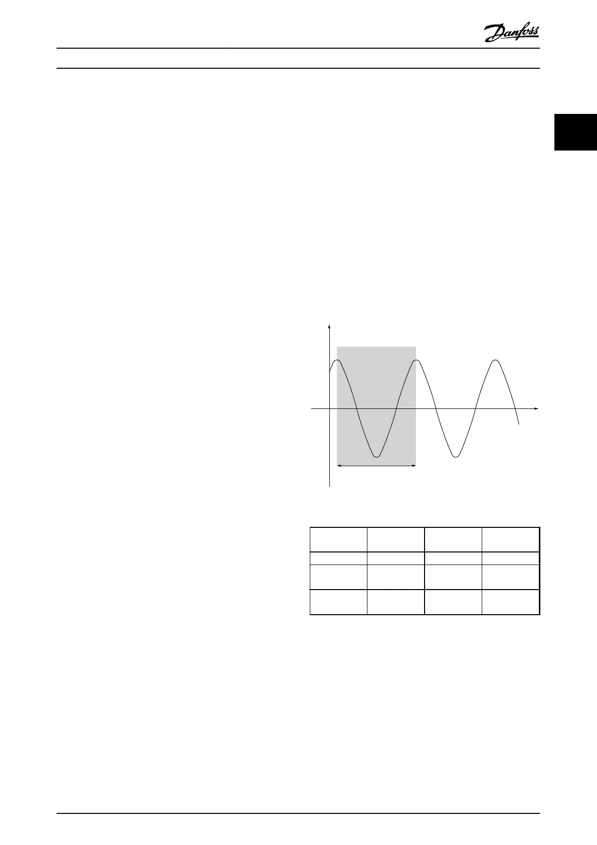
The period of the oscillation (P
u
) (called the ultimate
period) is determined as shown in Illustration 2.16 and
should be measured when the amplitude of oscillation is
quite small.
1. Select only proportional control, meaning that
the integral time is set to the maximum value,
while the differentiation time is set to 0.
2. Increase the value of the proportional gain until
the point of instability is reached (sustained
oscillations) and the critical value of gain, K
u
, is
reached.
3. Measure the period of oscillation to obtain the
critical time constant, P
u
.
4.
Use Table 2.9 to calculate the necessary PID
control parameters.
The process operator can do the final tuning of the control
iteratively to yield satisfactory control.
Illustration 2.16 Marginally Stable System
Type of
Control
Proportional
Gain
Integral Time Differentiation
Time
PI-control
0.45 * K
u
0.833 * P
u
-
PID tight
control
0.6 * K
u
0.5 * P
u
0.125 * P
u
PID some
overshoot
0.33 * K
u
0.5 * P
u
0.33 * P
u
Table 2.9 Ziegler Nichols Tuning for Regulator
Product Overview
VLT
®
AutomationDrive FC 360 Design Guide
MG06B202 - VLT
®
is a registered Danfoss trademark 31
2 2
 Loading...


