2.5.2 Process PID Control
The Process PID Control can be used to control application parameters that can be measured by a sensor (i.e. pressure,
temperature, flow) and be affected by the connected motor through a pump, fan or otherwise.
Table 2.6 shows the control configurations where the Process Control is possible. Refer to 2.3 Control Structures to see where
the Speed Control is active.
1-00 Configuration Mode 1-01 Motor Control Principle
U/f
VVC
plus
[3] Process N.A. Process
Table 2.6 Control Configuration
NOTE
The Process Control PID will work under the default parameter setting, but tuning the parameters is highly recommended
to optimise the application control performance.
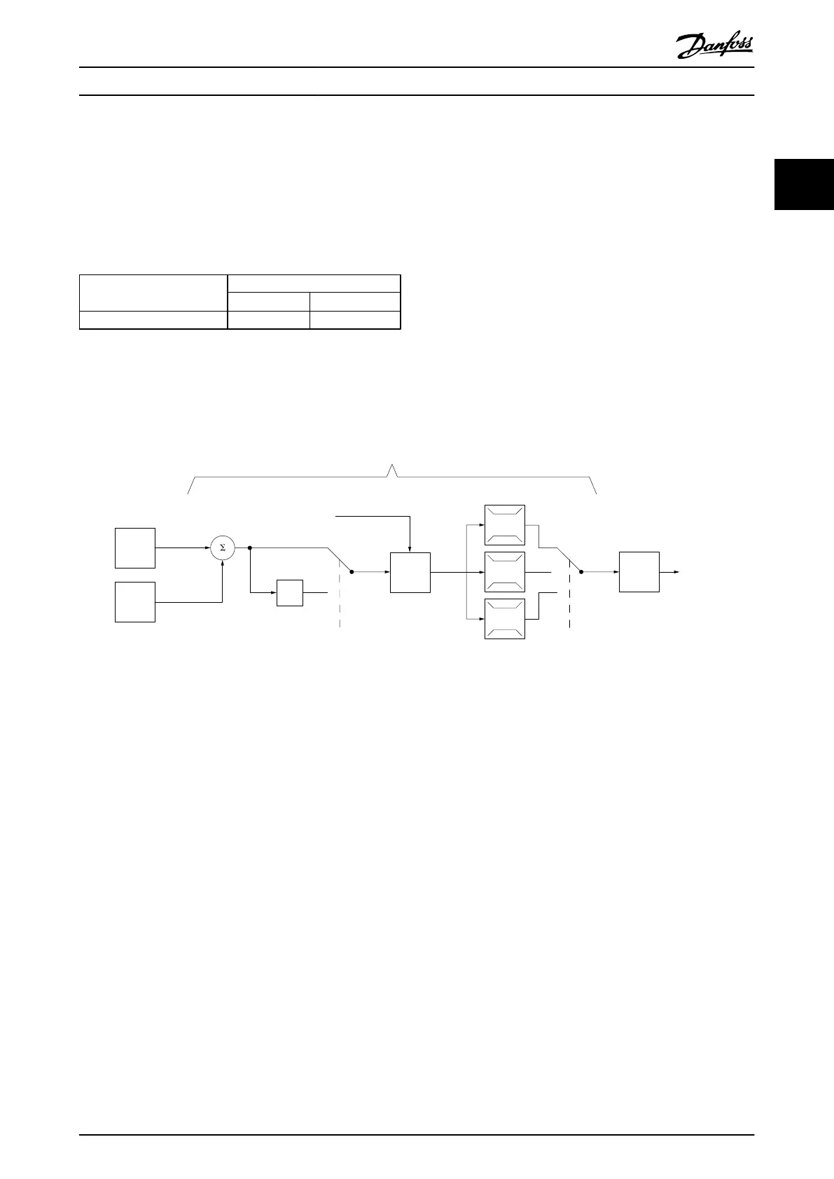
P 7-30
normal/inverse
PID
P 7-38
*(-1)
Feed forward
Ref.
Handling
Feedback
Handling
% [unit]
% [unit]
%
[unit]
%
[speed]
Scale to
speed
P 4-10
Motor speed
direction
To motor
control
Process PID
130BA178.10
_
+
0%
-100%
100%
0%
-100%
100%
Illustration 2.13 Process PID Control Diagram
Product Overview
VLT
®
AutomationDrive FC 360 Design Guide
MG06B202 - VLT
®
is a registered Danfoss trademark 27
2 2
 Loading...


