4.1.1 Encoder Connection
The purpose of this guideline is to ease the set-up of
encoder connection to the frequency converter. Before
setting up the encoder the basic settings for a closed loop
speed control system will be shown.
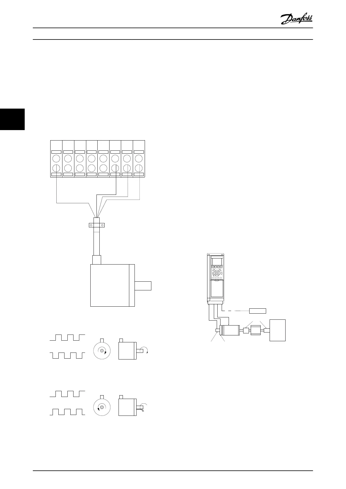
Encoder Connection to the frequency converter
130BD366.12
+24 V DC
A
B
GND
12 18 322719 29 33 20
Illustration 4.2 24 V or 10-30 V Encoder
Illustration 4.3 24 V Incremental Encoder. Max. Cable Length 5
m.
4.1.2
Encoder Direction
The direction of encoder is determined by which order the
pulses are entering the drive.
Clockwise direction means channel A is 90 electrical
degrees before channel B.
Counter Clockwise direction means channel B is 90
electrical degrees before A.
The direction determined by looking into the shaft end.
4.1.3 Closed Loop Drive System
A drive system consist usually of more elements such as:
•
Motor
•
Add
(Gearbox)
(Mechanical Brake)
•
Frequency converter
•
Encoder as feed-back system
•
Brake resistor for dynamic braking
•
Transmission
•
Load
Applications demanding mechanical brake control will
usually need a brake resistor.
Motor
Gearbox
Load
Transmission
Encoder Mech. brake
Brake resistor
130BA120.10
Illustration 4.4 Basic Set-up for Closed Loop Speed Control
Application Examples
VLT
®
AutomationDrive FC 360 Design Guide
62 MG06B202 - VLT
®
is a registered Danfoss trademark
44
 Loading...


