Parameters
FC
+24 V
D IN
D IN
D IN
COM
D IN
D IN
D IN
D IN
+10 V
A IN
A IN
COM
A OUT
12
18
19
20
27
29
32
33
31
50
53
54
55
42
130BD069.11
45
A OUT
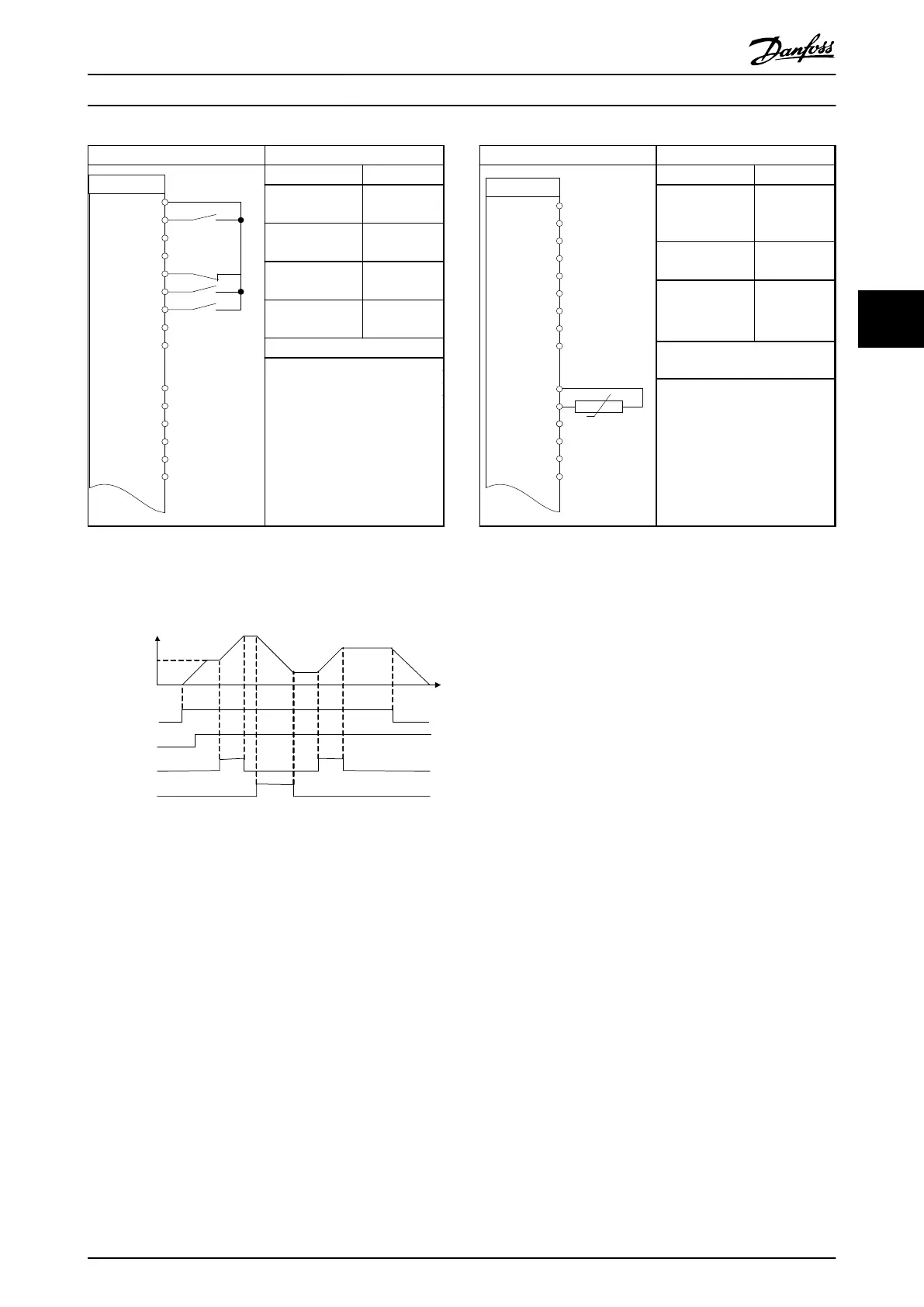
Function Setting
5-10 Terminal 18
Digital Input
[8] Start*
5-12 Terminal 27
Digital Input
[19] Freeze
Reference
5-13 Terminal 29
Digital Input
[21] Speed
Up
5-14 Terminal 32
Digital Input
[22] Speed
Down
* = Default Value
Notes/comments:
Table 4.8 Speed Up/Down
S t a r t ( 1 8 )
F r e e z e r e f ( 2 7 )
S p e e d u p ( 2 9 )
S p e e d d o w n ( 3 2 )
S p e e d
R e f e r e n c e
130BB840.10
Illustration 4.1 Speed Up/Down
Illustration for Table 4.8
CAUTION
Thermistors must use reinforced or double insulation to
meet PELV insulation requirements.
Parameters
130BD070.11
+24 V
D IN
D IN
D IN
COM
D IN
D IN
D IN
D IN
+10 V
A IN
A IN
COM
A OUT
12
18
19
20
27
29
32
33
31
50
53
54
55
42
FC
45
A OUT
Function Setting
1-90 Motor
Thermal
Protection
[2]
Thermistor
trip
1-93 Thermistor
Source
[1] Analog
input 53
6-19 Terminal 53
Mode
[1] Voltage
* = Default Value
Notes/comments:
If only a warning is desired,
1-90 Motor Thermal Protection
should be set to [1] Thermistor
warning.
Table 4.9 Motor Thermistor
Application Examples
VLT
®
AutomationDrive FC 360 Design Guide
MG06B202 - VLT
®
is a registered Danfoss trademark 61
4 4
 Loading...


