2.2 Electrical Installation
130BC438.12
3 Phase
power
input
Switch Mode
Power Supply
Motor
Analog Output
Interface
(PNP) = Source
(NPN) = Sink
ON=Terminated
OFF=Open
Brake
resistor
91 (L1)
92 (L2)
93 (L3)
PE
50 (+10 V OUT)
53 (A IN)
54 (A IN)
55 (COM A IN)
0/4-20 mA
12 (+24 V OUT)
31 (D IN)
18 (D IN)
20 (COM D IN)
10 V DC
15 mA 100 mA
+ - + -
(U) 96
(V) 97
(W) 98
(PE) 99
(A OUT) 45
(A OUT) 42
(P RS-485) 68
(N RS-485) 69
(COM RS-485) 61
0V
5V
S801
0/4-20 mA
RS-485
RS-485
03
+10 V DC
0/4-20 mA
0-10 V DC
24 V DC
02
01
05
04
240 V AC, 2 A
24 V (NPN)
0 V (PNP)
0 V (PNP)
24 V (NPN)
19 (D IN)
24 V (NPN)
0 V (PNP)
27
24 V
0 V
(D IN/OUT)
0 V (PNP)
24 V (NPN)
(D IN/OUT)
0 V
24 V
29
24 V (NPN)
0 V (PNP)
0 V (PNP)
24 V (NPN)
33 (D IN)
32 (D IN)
95
P 5-00
21
ON
(+UDC) 82
(BR) 81
24 V (NPN)
0 V (PNP)
0-10 V DC
(-UDC) 88
RFI
3)
0 V
240 V AC, 2 A
Relay 1
1)
Relay 2 2)
4)
06
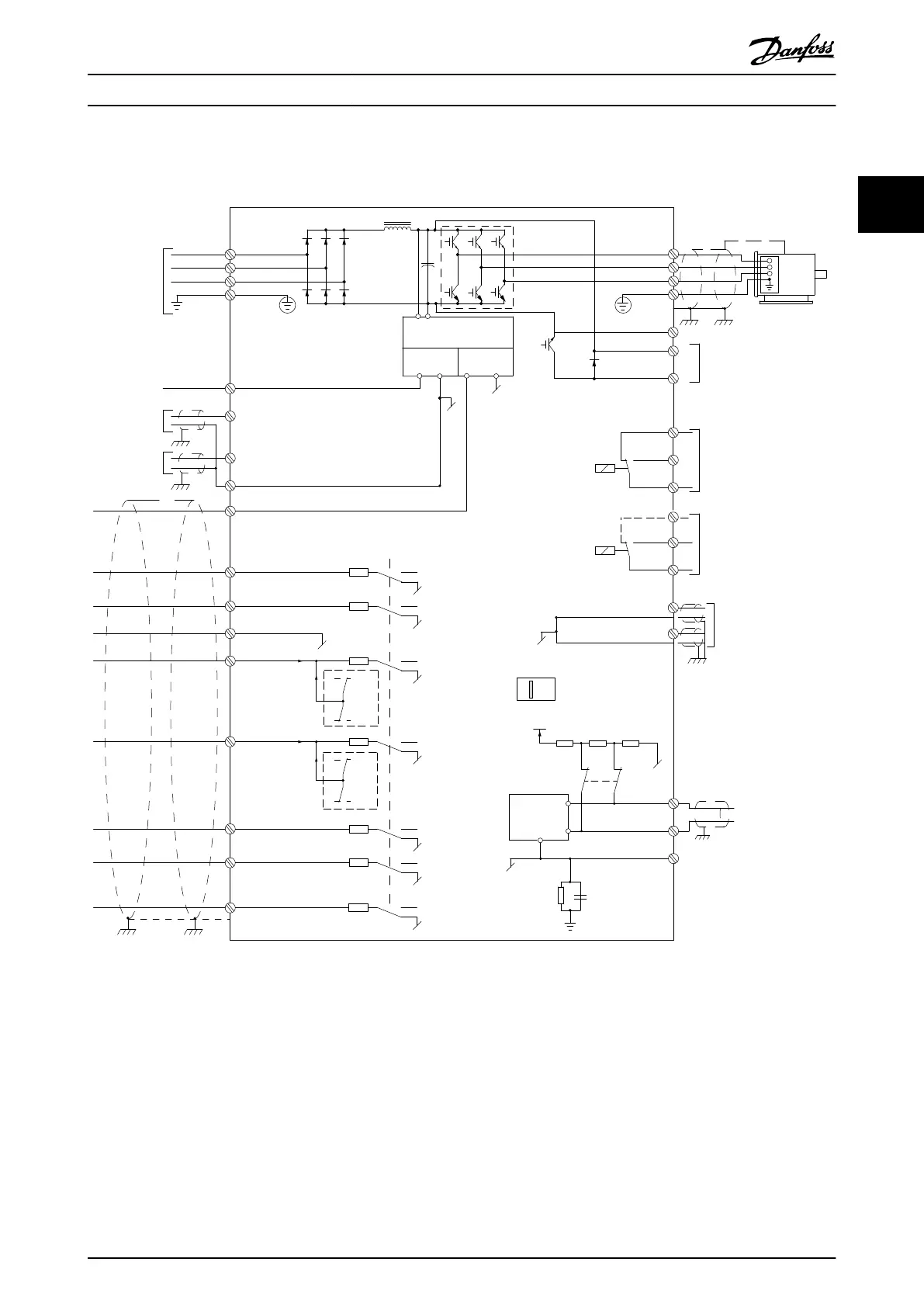
Illustration 2.1 Basic Wiring Schematic Drawing
A=Analog, D=Digital
1) Built-in brake chopper available from 0.37-22 kW
2) Relay 2 is 2 pole for J1-J3 and 3 pole for J4-J7. Relay 2 of J4-J7 with terminal 4, 5, 6, same NO/NC logic as Relay 1.
3) Dual DC choke in 30-75 kW
4) Switch S801 (bus terminal) can be used to enable termination on the RS-485 port (terminals 68 and 69).
Product Overview
VLT
®
AutomationDrive FC 360 Design Guide
MG06B202 - VLT
®
is a registered Danfoss trademark 13
2 2
 Loading...


