controlled by frequency converters. The FC 360 also
complies with IEC 60034-17 regarding Norm motors
controlled by frequency converters
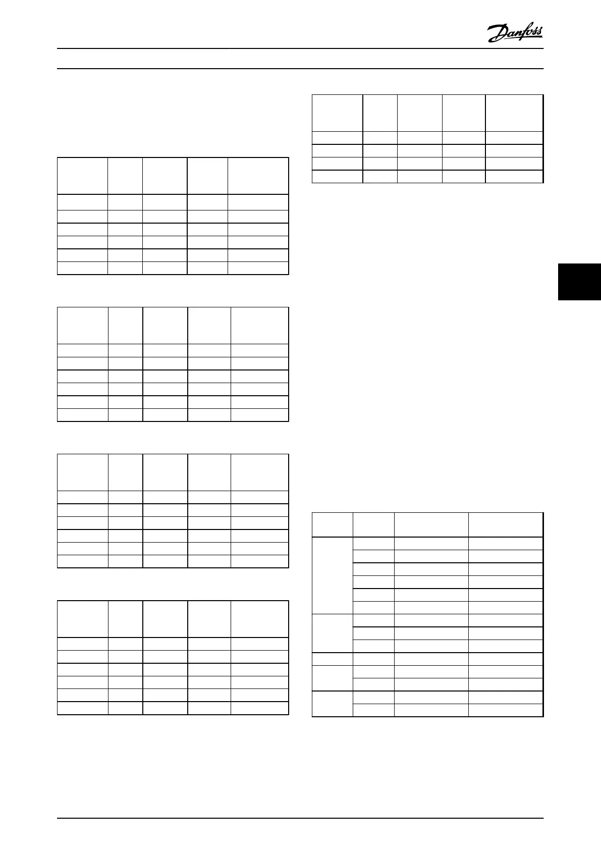
Measured values from lab tests:
Cable
length [m]
Mains
voltage
[V]
Rise time
[μsec]
Upeak
[kV]
dU/dt
[kV/μsec]
5 400 0.164 0.98 5.4
50 400 0.292 1.04 2.81
5 400 0.184 1.2 5.27
50 400 0.352 1.42 3.19
5 480 0.168 1.09 5.27
50 480 0.32 1.23 3.08
Table 6.7 FC 360, 2.2 kW T4
Cable
length [m]
Mains
voltage
[V]
Rise time
[μsec]
Upeak
[kV]
dU/dt
[kV/μsec]
5 400 0.18 0.86 3.84
50 400 0.376 0.96 2.08
5 400 0.232 1.03 3.54
50 400 0.432 1.43 2.64
5 480 0.196 0.97 3.98
50 480 0.38 1.19 2.5
Table 6.8 FC 360, 5.5 kW T4
Cable
length [m]
Mains
voltage
[V]
Rise time
[μsec]
Upeak
[kV]
dU/dt
[kV/μsec]
5 400 0.166 0.992 4.85
50 400 0.372 1.08 2.33
5 400 0.188 1.19 5.24
50 400 0.36 1.46 3.25
5 480 0.168 1.1 5.2
50 480 0.352 1.25 2.85
Table 6.9 FC 360, 7.5 kW T4
Cable
length [m]
Mains
voltage
[V]
Rise time
[μsec]
Upeak
[kV]
dU/dt
[kV/μsec]
5 400 0.224 0.99 3.54
50 400 0.392 1.07 2.19
5 400 0.332 0.855 2.07
50 400 0.456 1.51 2.65
5 480 0.236 1.14 3.87
50 480 0.408 1.33 2.61
Table 6.10 FC 360, 15 kW T4
Cable
length [m]
Mains
voltage
[V]
Rise time
[μsec]
Upeak
[kV]
dU/dt
[kV/μsec]
5 400 0.98 2.8
50 400 1.04 2.4
5 480 1.09 2.6
50 480 1.23 2.6
Table 6.11 FC 360, 22 kW T4
6.7 Special Conditions
Under some special conditions, where the operation of the
frequency converter is challenged, derating must be taken
into account. In some conditions, derating must be done
manually.
In other conditions, the frequency converter automatically
performs a degree of derating when necessary. This is
done in order to ensure the performance at critical stages
where the alternative could be a trip.
6.7.1
Manual Derating
Manual derating must be considered for:
•
Air pressure – for installation at altitudes above 1
km
•
Motor speed – at continuous operation at low
RPM in constant torque applications
•
Ambient temperature – above 45 °C (for some
types above 50 °C), for details, see Table 6.12 and
Table 6.13.
Frame size
Power size
[kW]
Max. output current
at 45 °C
Max. output current
at 50 °C
J1
0.37 1.2 1.2
0.55 1.7 1.7
0.75 2.2 2.2
1.1 3.0 3.0
1.5 3.7 3.0
2.2 5.3 4.1
J2
3 7.2 7.2
4 9.0 9.0
5.5 12.0 10.2
J3 7.5 15.5 13.1
J4
11 23.0 23.0
15 31.0 26.0
J5
18.5 37.0 37.0
22 42.5 40.0
Table 6.12 Derating at 380 V
Specifications
VLT
®
AutomationDrive FC 360 Design Guide
MG06B202 - VLT
®
is a registered Danfoss trademark 75
6
6
 Loading...


