The remote reference is calculated once every scan
interval and initially consists of two types of reference
inputs:
1. X (the external reference): A sum (see
3-04 Reference Function) of up to 4 externally
selected references, comprising any combination
(determined by the setting of 3-15 Reference 1
Source, 3-16 Reference 2 Source and 3-17 Reference
3 Source) of a fixed preset reference (3-10 Preset
Reference), variable analog references, variable
digital pulse references, and various serial bus
references in whatever unit the frequency
converter is controlled ([Hz], [RPM], [Nm] etc.).
2. Y- (the relative reference): A sum of one fixed
preset reference (3-14 Preset Relative Reference)
and one variable analog reference (3-18 Relative
Scaling Reference Source) in [%].
The two types of reference inputs are combined in the
following formula: Remote reference = X + X * Y / 100%. If
relative reference is not used, set 3-18 Relative Scaling
Reference Source to [0] No function and 3-14 Preset Relative
Reference to 0%. The catch up/slow down function and the
freeze reference function can both be activated by digital
inputs on the frequency converter. The functions and
parameters are described in the VLT
®
AutomationDrive FC
360 Programming Guide.
The scaling of analog references are described in
parameter groups 6-1* Analog Input 53 and 6-2* Analog
Input 54, and the scaling of digital pulse references are
described in parameter group 5-5* Pulse Input.
Reference limits and ranges are set in parameter group
3-0* Reference Limits.
2.4.1
Reference Limits
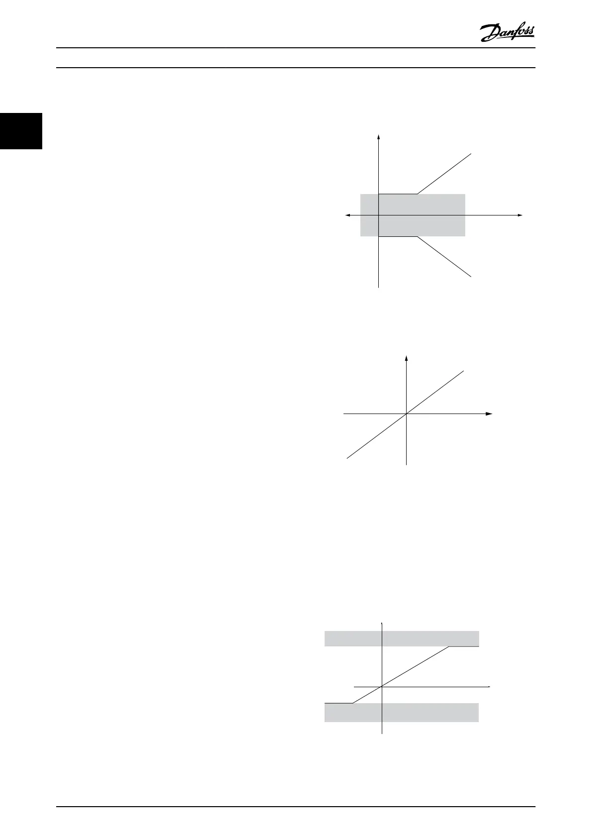
3-00 Reference Range, 3-02 Minimum Reference and
3-03 Maximum Reference together define the allowed range
of the sum of all references. The sum of all references are
clamped when necessary. The relation between the
resulting reference (after clamping) and the sum of all
references is shown in Illustration 2.5 and Illustration 2.6.
Resulting reference
Sum of all
references
Forward
Reverse
P 3-00 Reference Range= [0] Min-Max
130BA184.10
-P 3-03
P 3-03
P 3-02
-P 3-02
Illustration 2.5 Sum of all References
P 3-00 Reference Range =[1]-Max-Max
Resulting reference
Sum of all
references
-P 3-03
P 3-03
130BA185.10
Illustration 2.6 Sum of all References
The value of 3-02 Minimum Reference cannot be set to less
than 0, unless 1-00 Configuration Mode is set to [3] Process.
In that case, the following relations between the resulting
reference (after clamping) and the sum of all references is
as shown in Illustration 2.7.
130BA186.11
P 3-03
P 3-02
Sum of all
references
P 3-00 Reference Range= [0] Min to Max
Resulting reference
Illustration 2.7 Sum of all References
Product Overview
VLT
®
AutomationDrive FC 360 Design Guide
18 MG06B202 - VLT
®
is a registered Danfoss trademark
22
 Loading...


