1.2 Definitions
1.2.1 Frequency Converter
I
VLT, MAX
Maximum output current.
I
VLT,N
Rated output current supplied by the frequency converter.
U
VLT,MAX
Maximum output voltage.
1.2.2
Input
Control command
Start and stop the connected motor by means of LCP and
digital inputs.
Functions are divided into two groups.
Functions in group 1 have higher priority than functions in
group 2.
Group 1 Reset, Coasting stop, Reset and Coasting stop,
Quick-stop, DC braking, Stop and the [OFF] key.
Group 2 Start, Pulse start, Reversing, Start reversing, Jog
and Freeze output
1.2.3 Motor
Motor Running
Torque generated on output shaft and speed from zero
rpm to max. speed on motor.
f
JOG
Motor frequency when the jog function is activated (via
digital terminals).
f
M
Motor frequency.
f
MAX
Maximum motor frequency.
f
MIN
Minimum motor frequency.
f
M,N
Rated motor frequency (nameplate data).
I
M
Motor current (actual).
I
M,N
Rated motor current (nameplate data).
n
M,N
Rated motor speed (nameplate data).
n
s
Synchronous motor speed
n
s
=
2 ×
par
. 1 − 23 × 60
s
par
. 1 − 39
n
slip
Motor slip.
P
M,N
Rated motor power (nameplate data in kW or HP).
T
M,N
Rated torque (motor).
U
M
Instantaneous motor voltage.
U
M,N
Rated motor voltage (nameplate data).
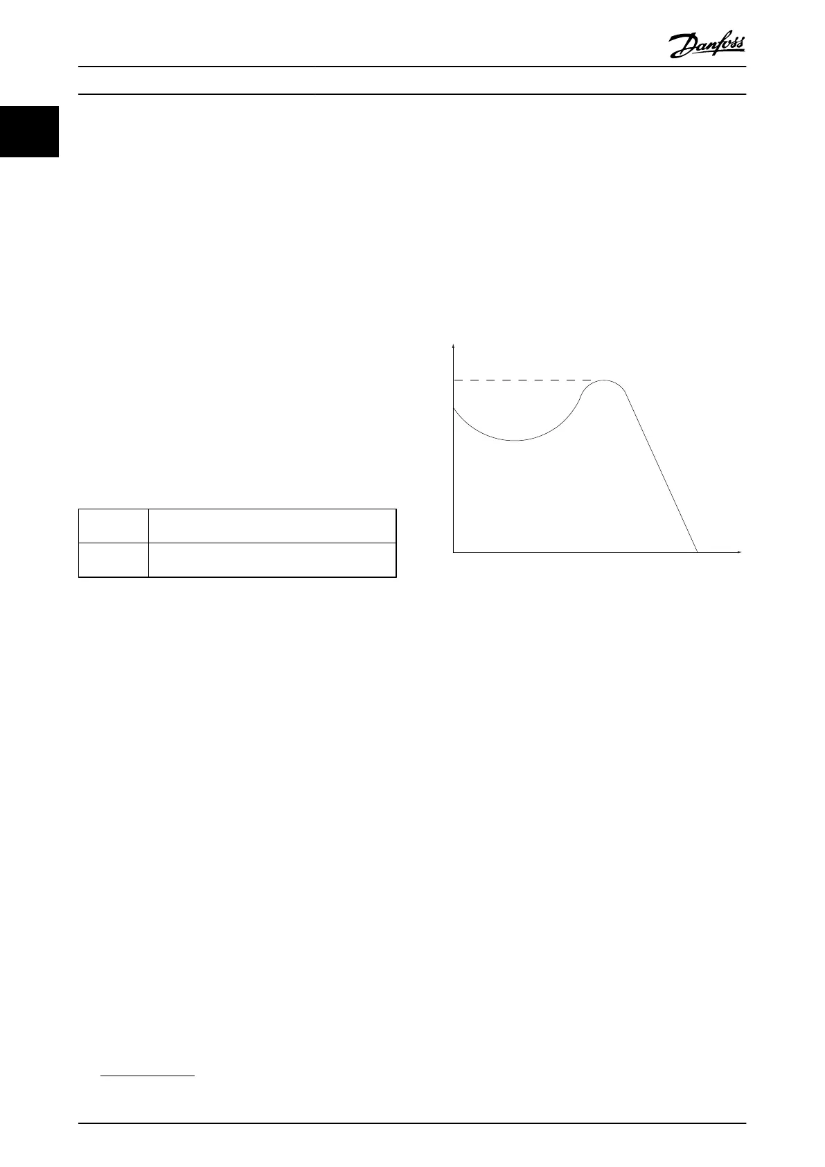
175ZA078.10
Pull-out
rpm
Torque
Illustration 1.1 Break-away Torque
Break-away torque
η
VLT
The efficiency of the frequency converter is defined as the
ratio between the power output and the power input.
Start-disable command
A stop command belonging to the group 1 control
commands - see this group.
Stop command
See Control commands.
1.2.4
References
Analog Reference
A signal transmitted to the analog inputs 53 or 54, can be
voltage or current.
Binary Reference
A signal transmitted to the serial communication port.
Preset Reference
A defined preset reference to be set from -100% to +100%
of the reference range. Selection of eight preset references
via the digital terminals.
Pulse Reference
A pulse frequency signal transmitted to the digital inputs
(terminal 29 or 33).
Introduction
VLT
®
AutomationDrive FC 360 Design Guide
6 MG06B202 - VLT
®
is a registered Danfoss trademark
11
 Loading...


