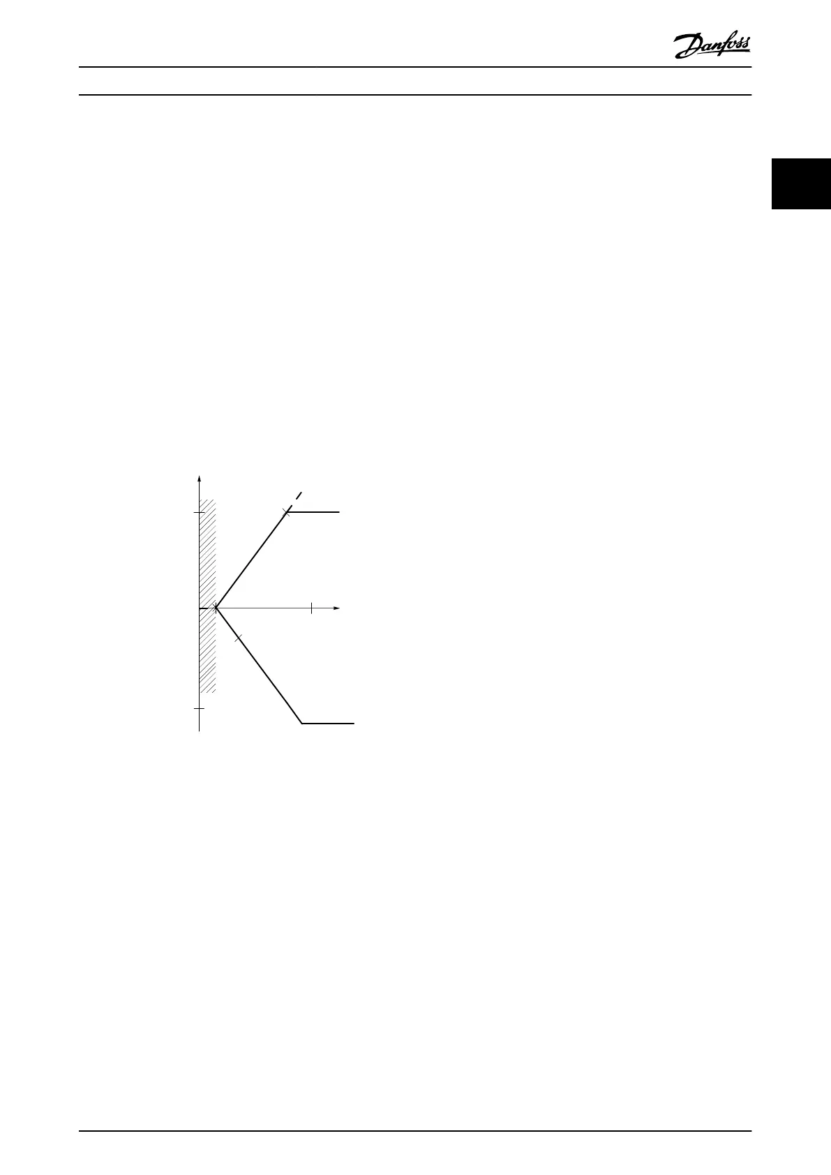
2.4.4 Dead Band Around Zero
In some cases the reference (in rare cases also the
feedback) should have a dead band around zero (i.e. to
make sure the machine is stopped when the reference is
“near zero”).
To make the dead band active and to set the amount of
dead band, the following settings must be done:
•
Either minimum reference value (see Table 2.2 for
relevant parameter) or maximum reference value
must be zero. In other words; Either P1 or P2
must be on the X-axis in Illustration 2.9.
•
And both points defining the scaling graph are in
the same quadrant.
The size of the Dead Band is defined by either P1 or P2 as
shown in Illustration 2.9.
Resource output
[Hz] or “No unit”
Resource input
[mA]
Quadrant 2
Quadrant 3
Quadrant 1
Quadrant 4
Terminal X high
Low reference/feedback
value
High reference/feedback
value
1
-50
16
50
20
P1
P2
0
130BD446.10
forward
reverse
Terminal low
Illustration 2.9 Size of Dead Band
Product Overview
VLT
®
AutomationDrive FC 360 Design Guide
MG06B202 - VLT
®
is a registered Danfoss trademark 21
2 2
 Loading...


