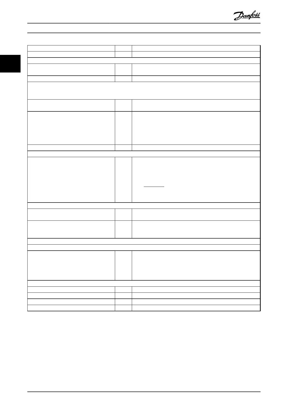
Function Par. no. Setting
Initialize the frequency converter 14-22 [2] Initialization - make a power cycling - press reset
1) Set motor parameters:
Set the motor parameters according to name plate
data
1-2* As stated on motor name plate
Perform a full Automation Motor Adaptation 1-29 [1] Enable complete AMA
2) Check that motor is running in the right direction.
When motor is connected to frequency converter with straight forward phase order as U - U; V- V; W - W motor shaft usually turns
clockwise seen into shaft end.
Press [Hand On]. Check shaft direction by applying
a manual reference.
If motor turns opposite of required direction:
1.
Change motor direction in 4-10 Motor Speed
Direction
2. Turn off mains - wait for DC link to discharge -
switch two of the motor phases
4-10 Select correct motor shaft direction
Set configuration mode 1-00 [3] Process
3) Set reference configuration, ie. the range for reference handling. Set scaling of analog input in parameter 6-xx
Set reference/feedback units
Set min. reference (10 °C)
Set max. reference (80 °C)
If set value is determined from a preset value
(array parameter), set other reference sources to
No Function
3-01
3-02
3-03
3-10
[60] ° C Unit shown on display
-5° C
35° C
[0] 35%
Ref
=
Par
. 3 − 10
(
0
)
100
×
((
Par
. 3 − 03
)
−
(
par
. 3 − 02
))
= 24, 5°
C
3-14 Preset Relative Reference to 3-18 Relative Scaling Reference Resource [0]
= No Function
4) Adjust limits for the frequency converter:
Set ramp times to an appropriate value as 20 s 3-41
3-42
20 s
20 s
Set min. speed limits
Set motor speed max. limit
Set max. output frequency
4-12
4-14
4-19
10 Hz
50 Hz
60 Hz
Set 6-19 Terminal 53 mode and 6-29 Terminal 54 mode to voltage or current mode.
5) Scale analog inputs used for reference and feedback
Set terminal 53 low voltage
Set terminal 53 high voltage
Set terminal 54 low feedback value
Set terminal 54 high feedback value
Set feedback source
6-10
6-11
6-24
6-25
7-20
0V
10V
-5° C
35° C
[2] Analog input 54
6) Basic PID settings
Process PID Normal/Inverse 7-30 [0] Normal
Process PID Anti Wind-up 7-31 [1] On
Process PID start speed 7-32 300 rpm
Save parameters to LCP 0-50 [1] All to LCP
Table 2.8 Example of Process PID Control Set-up
Product Overview
VLT
®
AutomationDrive FC 360 Design Guide
30 MG06B202 - VLT
®
is a registered Danfoss trademark
22
 Loading...


