Page 48 of 56
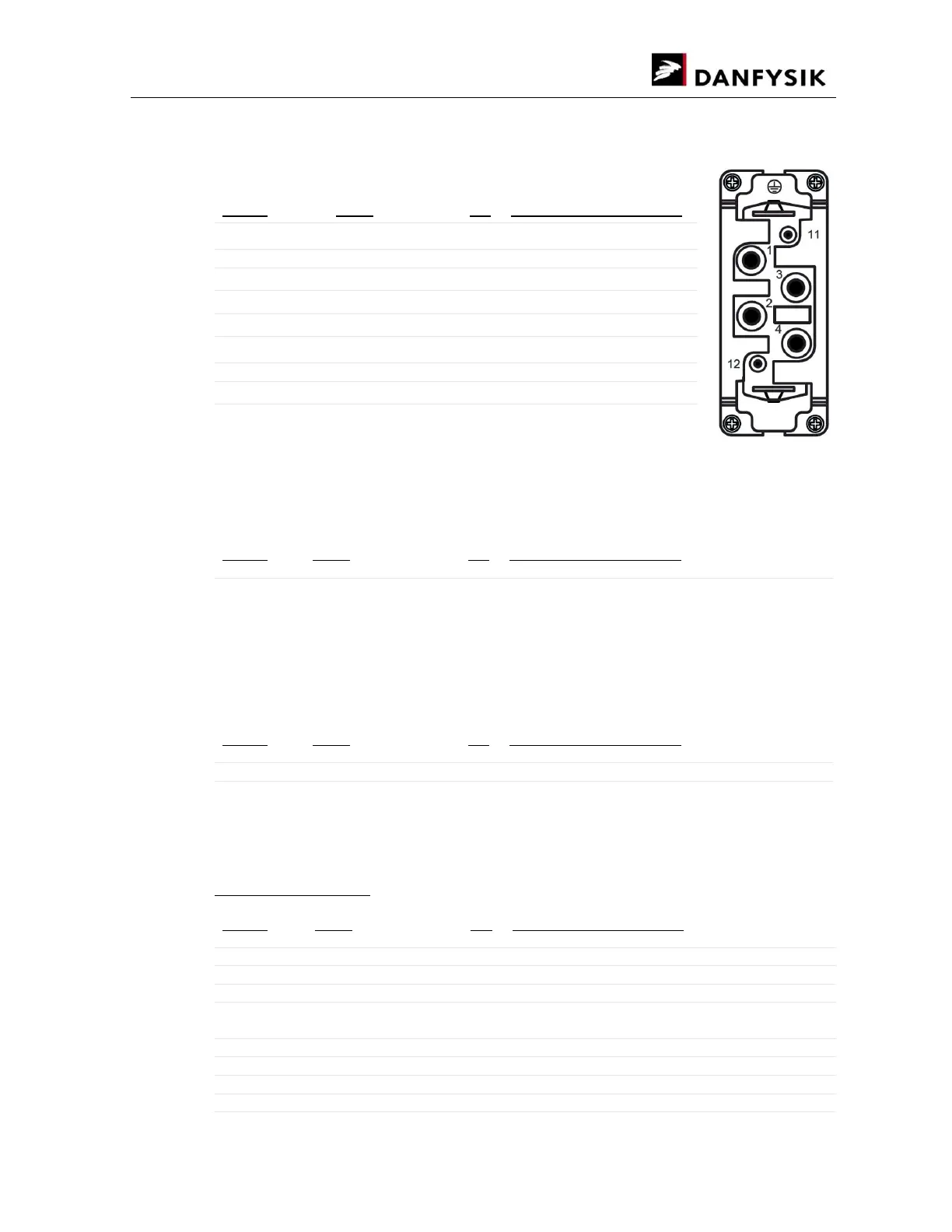
5.1.1. AC Mains connector X1:
The power connector for 400VAC mains and 230VAC control input
Pin no: Name I/O Description & Specification
Main power
1 NU
2 400 VAC 3-phase AC main input, L1
3 400 VAC 3-phase AC main input, L2
4 400 VAC 3-phase AC main input, L3
Control power
11 230 VAC Control input, Phase
12 230 VAC Control input, Neutral
Clips * Earth
*At the top and bottom of the connector.
5.1.2. Fuse holder F1:
Fuse for control power
Pin no: Name I/O Description & Specification
F1 Fuse for control power (2A/250V)
5.1.3. Output X24 and X25
The output bus bars of the control and power units should be connected using the bus bars
provided. The positive polarity terminal of the control unit should be connected to the positive
terminal of the power unit(s). Vice versa with the negative terminal, as shown in the fig.
Pin no: Name I/O Description & Specification
X24 O Positive polarity
X25 O Negative polarity
5.1.4. Link connection X108 on Control unit and X17 on Power Unit
The link connection is made between X108 on the control unit and X17 on the power unit.
X108 on control unit:
Pin no: Name I/O Description & Specification
1 OverTemperature interlock I Over temperature Interlock from slave(s)
2 AC failure interlock I AC fault from slave(s)
3 OverCurrent interlock I Over current Interlock from slave(s)
4 Ready O 5 V Logic Level - CMOS, NMOS, and TTL
compatible
5 ON O ON signal to slave(s)
6 COM O GNDD
7 I Monitor O Output current monitoring
8 RTN (GND) O GNDA Return line