Page 14 of 56
3.2. Operating with the Manual Control Panel
The MANUAL CONTROL PANEL (M-Panel Graphical) is an interface module used with several
Danfysik Magnet Power Supplies including the SYSTEM 9700.
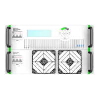
The SYSTEM 9700 comes with an M-panel as standard. It can however also be delivered with a
display board. This has two 5 digits 7 segment displays for voltage and current. LED indicators
for POWER ON, FAULT and READY. With this display board, the SYSTEM 9700 can be operated
remotely from a PC, or by connecting an M-panel to the local port situated on the backside of
the SYSTEM 9700. The M-panel can be connected and disconnected from the Power Supply
without affecting the power supply operation. Communication between the Power Supply and
the M-Panel is by a serial link, and may be physically located at the Power Supply or up to 400
meters away from it.
3.2.1. Main power ON / OFF and interlock RESET
The basic function of the M-panel is to turn the power supply ON / OFF and to RESET pending
interlocks. All controlled from a single button. For further information about the button
locations, see chapter 3.2.3 Front Panel Control.
Setting the output current is done through one of the pull-down menus described in the next
chapter.
When the power supply is ON, the LED in the button area will be lit.
When the power supply is OFF, the LED in the button area will be lit.
If an interlock is present, the LED inside the RESET button will be lit.
Pressing the RESET button will clear the interlocks that are no longer pending.
HINT
If an interlock is present, it will also be represented on the display at the lower right corner.
HINT
The colour of the LEDs can be reprogrammed to display green, red or orange.
3.2.2. Using the Manual Panel Menus
This chapter briefly describes the use of the M-Panel. The menus themselves are described
later.
The user interface of the M-Panel is based on a pull-down menu structure.
Press the MENU button to view the menus (if not already visible in the menu window).
To stop the main display from concealing the menus (set current, output current and voltage),
the pull-down menus are always displayed left aligned, i.e. the menu bar rolls over the pull-
down region.
With the menu bar visible:
Press the left “” or right “” arrow keys to display the selected pull-down menu on
the left side. At the bottom right, a help text shows the function of the selected drop-
down menu group.