System 9700 User Manual
Page 35 of 56
3.3.2. Data communication
The SYSTEM 9700 uses the standard serial interface RS422 that is compatible with many
computers and terminals. Besides RS422, SYSTEM 9700 supports RS232 and RS485.
The connectors for the serial interface ports “REMOTE CONTROL” and “LOCAL CONTROL” are
found at the back of the power supply.
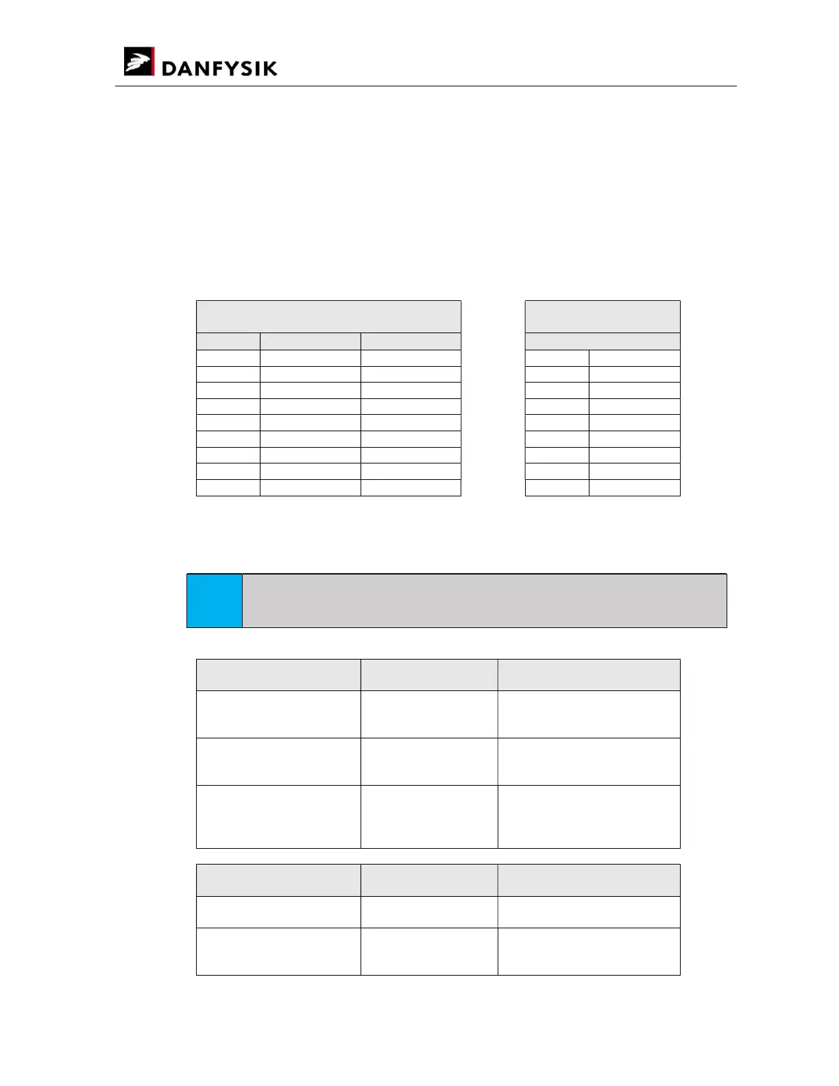
Pin descriptions of the RS232 and RS422 for the connector DB25S at the back of the power supply
are as follow.
REMOTE CONTROL
DB25
LOCAL CONTROL
DB9
RS422/RS485 RS232 RS422/RS485
Pin No. Signal Signal Pin No. Signal
2 TX 2 /TX_LOC
3 RX 3 TX_LOC
7 RETURN RETURN 4 /RX_LOC
9 TX_REM 5 RX_LOC
10 /TX_REM 6-7 +15V
11 RX_REM 8-9 -15V
12 /RX_REM
13 Vcc Vcc
Rx : Signals received by the Control Module from its host.
Tx : Signals transmitted by the Control Module to its host.
NOTE
The selection between RS232, RS422 and RS485 is made through solder straps on the
Control Board
Serial interface
in REMOTE mode
Strap REMOTE CONTROL
DB25
RS232 ST 330 : Close
ST 324 : Open
ST 325 : Open
Pin 2 TX
Pin 3 RX
2-Wire RS485 ST 324 : Close
ST 325 : Open
ST 330 : Open
Pin 9 TX_REM
Pin 11 RX_REM
4-Wire RS422/RS485 ST 325 : Close
ST 324 : Open
ST 330 : Open
Pin 9 TX_REM
Pin 10 /TX_REM
Pin 11 RX_REM
Pin 12 /RX_REM
Serial interface
in LOCAL mode
Strap LOCAL CONTROL
DB9
2-Wire RS485 ST 334 : Close
ST 339 : Open
Pin 3 TX_REM
Pin 5 RX_REM
4-Wire RS422/RS485 ST 339 : Close
ST 334 : Open
Pin 3 TX_REM
Pin 2 /TX_REM
Pin 5 RX_REM