DK-40 USER MANUAL V2.6 (02.08.2011)
K13D01-E - 32 -
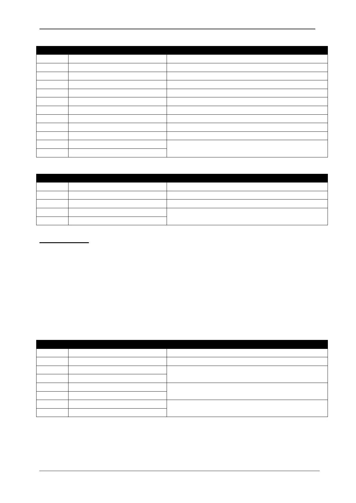
The normal response will be:
0 Controller address same as in the query
1 Function code 3
2 Data lenght in
(L) number of registers * 2
3 High byte of 1st register
4 Low byte of 1st register
5 High byte of 2nd register
6 Low byte of 2nd register
....
L+1 High byte of the last register
L+2 Low byte of the last register
L+3 CRC low byte See below for the checksum calculation
L+4 CRC high byte
The exceptional response will be:
0 Controller address same as in the query
1 Function code 131 (function code + 128)
2 Exception code 2 (illegal address)
3 CRC low byte See below for the checksum calculation
4 CRC high byte
Data Writing
The function 06 (write single register) or function 10 (write multiple registers) is used for
data writing. A maximum of 32 registers can be written at a time.
The MODBUS master will send a query containing data to be written. The answer will be
one of the below:
-A normal response confirming successful write,
-An exceptional response indicating a write error.
Only some of the available registers are authorized to be written. An attempt to write a write
protected register will result to the exceptional response.
The query message specifies the register address and data. The message structure is
below:
0 Controller address 1 to 254
1 Function code 6
2 Register address high See below the description of available registers
3 Register address low
4 Data high byte
5 Data low byte
6 CRC low byte See below for the checksum calculation
7 CRC high byte