DK-40 USER MANUAL V2.6 (02.08.2011)
K13D01-E - 33 -
Here is the sequence to write the value 0010h to the register 40h (64 decimal):
01 06 00 40 00 10 89 D2 (each byte is expressed as 2 hexadecimal characters)
The checksum value in the above message may be used for the verification of checksum
calculation algorithm
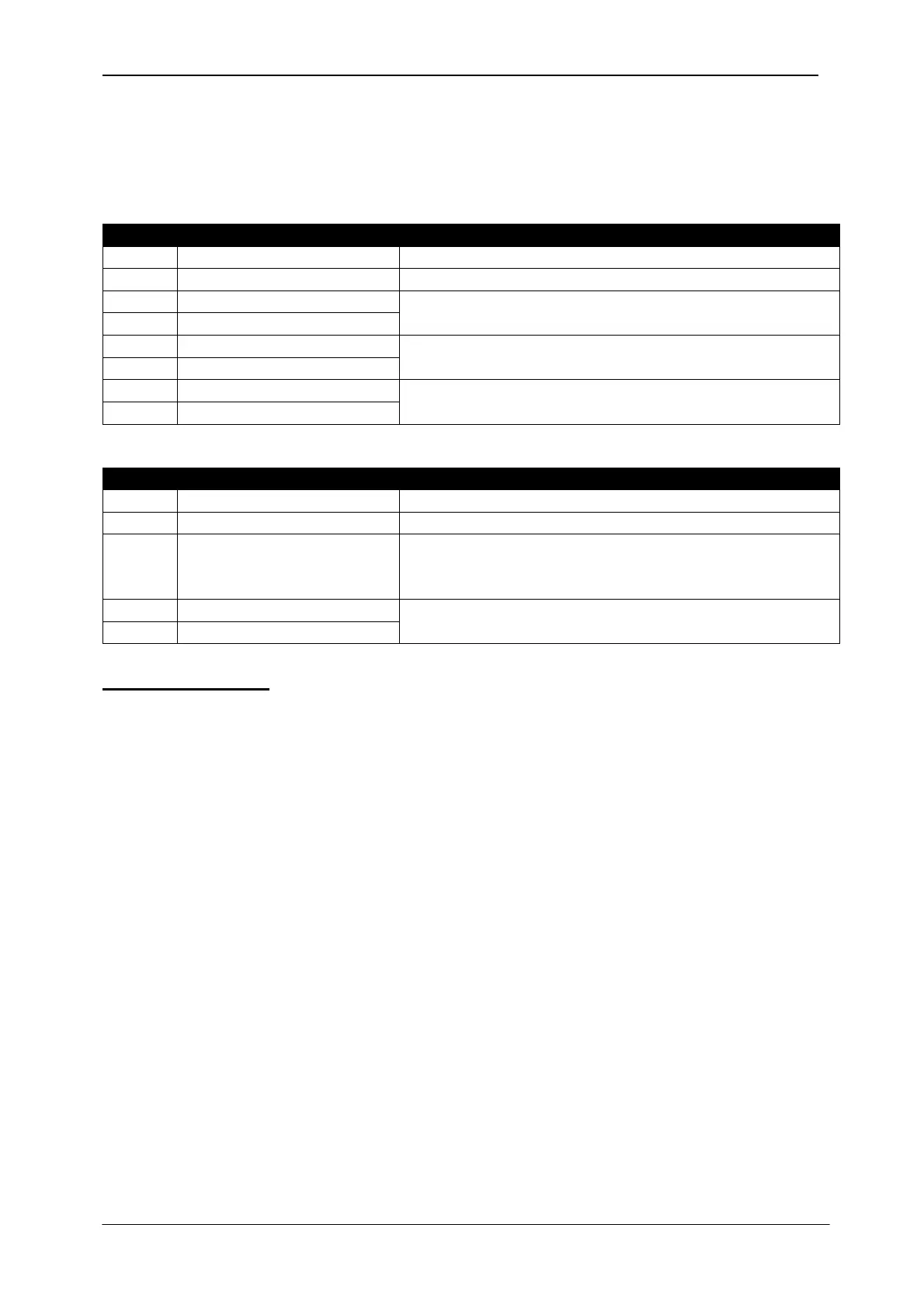
The normal response will be the same as the query:
0 Controller address 1 to 254
1 Function code 6
2 Register address high See below the description of available registers
3 Register address low
4 Data high byte
5 Data low byte
6 CRC low byte See below for the checksum calculation
7 CRC high byte
The exceptional response will be:
0 Controller address same as in the query
1 Function code 134 (function code + 128)
2 Exception code 2 (illegal address)
or
10 (write protection)
3 CRC low byte See below for the checksum calculation
4 CRC high byte
CRC calculation
Here is a procedure for generating a CRC:
1) Load a 16–bit register with FFFF hex (all 1’s). Call this the CRC register.
2) Exclusive OR the first 8–bit byte of the message (the function code byte) with the low–
order byte of the 16–bit CRC register, putting the result in the CRC register.
3) Shift the CRC register one bit to the right (toward the LSB), zero–filling the MSB. Extract
and examine the LSB. The LSB is the least significant bit of the CRC before the shift
operation.
4) If the LSB is 1: Exclusive OR the CRC register with the polynomial value A001 hex.
5) Repeat Steps 3 and 4 until 8 shifts have been performed. Thus, a complete 8–bit byte
will be processed.
6) Repeat Steps 2 through 5 for the next 8–bit byte of the message. Continue doing this
until all bytes have been processed.
7) The final contents of the CRC register is the CRC value.
8) Place the CRC into the message such that the low byte is transmitted first. The algorithm
should give the correct CRC for below messages:
01 03 00 20 00 10 45 CC
01 06 00 40 00 10 89 D2