MATRIX 210™ QUICK GUIDE
6
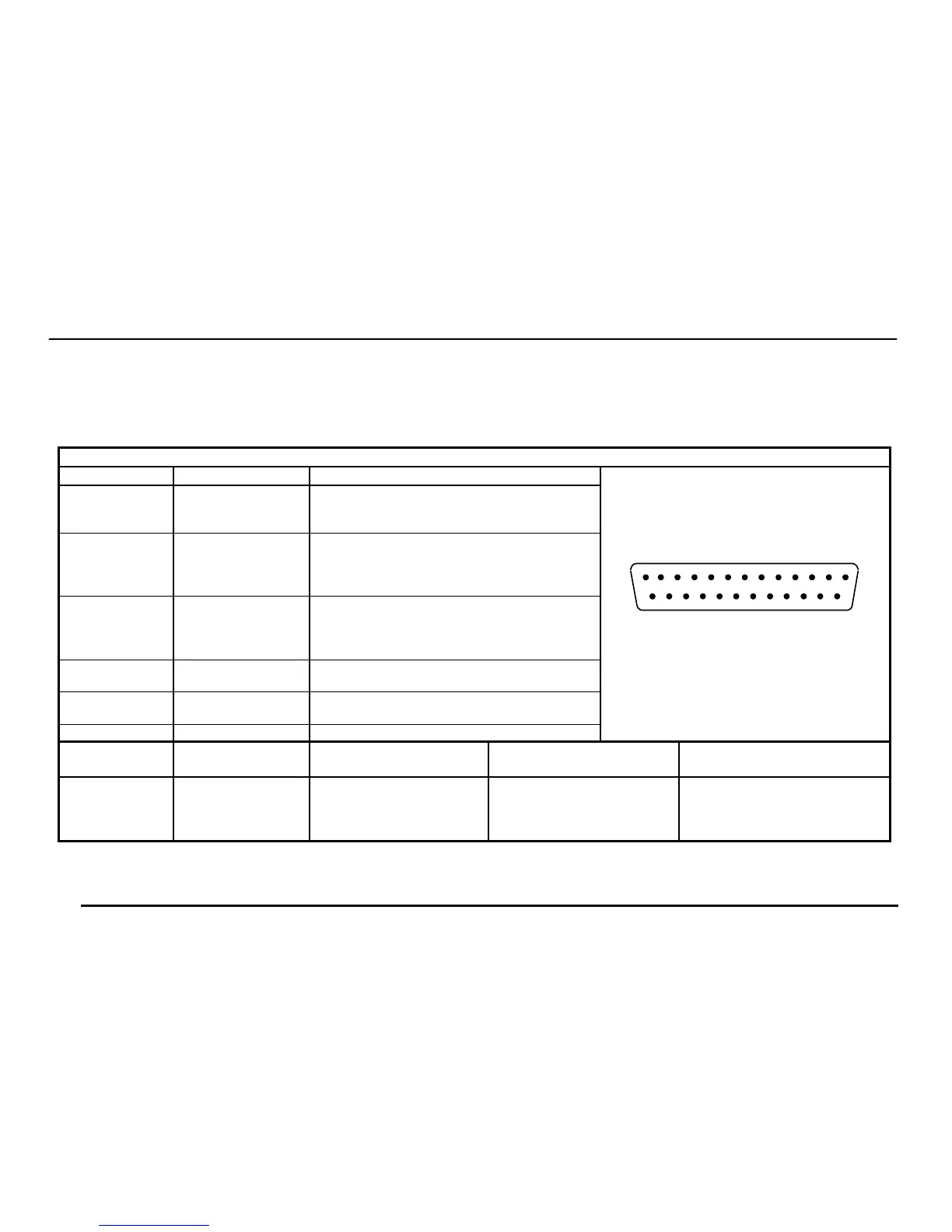
25-Pin Connector Pinout for Matrix 210™ 25-Pin Models
The table below gives the pinout of the 25-pin male D-sub connector for connection to the power supply and input/output signals.
Use this pinout when the Matrix 210™ reader is connected by means of the 25-pin connector:
25-pin D-sub male connector pinout
Pin Name Function
13, 9 Vdc Power supply input voltage +
25, 7 GND Power supply input voltage -
1 CHASSIS Cable shield connected to chassis
18 I1A External Trigger A (polarity insensitive)
19 I1B External Trigger B (polarity insensitive)
6 I2A Input 2 A (polarity insensitive)
10 I2B Input 2 B (polarity insensitive)
8 O1+ Output 1 +
22 O1- Output 1 -
11 O2+ Output 2 +
12 O2- Output 2 -
20 RX Auxiliary RS232 RX
21 TX Auxiliary RS232 TX
23 ID+ ID-NET™ network +
24 ID- ID-NET™ network -
14, 15, 16, 17 NC Not Connected
13
25 14
1
Figure 2 - 25-pin Male D-sub Connector
Pin Name RS232
RS485
Full-Duplex
RS485
Half-Duplex
2 TX TX+ RTX+
3 RX *RX+
4 RTS TX- RTX-
5
MAIN INTERFACE
(SW SELECTABLE)
CTS *RX-
* Do not leave floating, see Reference Manual for connection details.

 Loading...


