AP25 Installation and Operating Guide Version 1.00
Appendix F. H338 Optical Film Card Option F-8 Document #: 9301H79500 Ver. 1.00
Prior to optical alignment, verify all wiring and connections are correct. Shielded cables such as
Belden 8451 or similar should be used.
The right channel is nearest the edge of the film. To confirm proper wiring, while observing the
projector output on a RTA or the AP25 setup screen, place a business card or similar object to block
the side of the cell nearest the edge of the film. You should detect a large drop in the right channel
level.
Although white light tungsten type exciter lamps have been replaced in projectors with Red LED
readers the adjustment and calibrations remain similar. Making adjustments to the film optics will
vary depending on the manufacturer; it is recommended that a review of the manufacturer’s
recommended alignment adjustments be reviewed prior to making any mechanical changes on the
optical head on the projector.
F4.4. Mechanical Optical Alignment
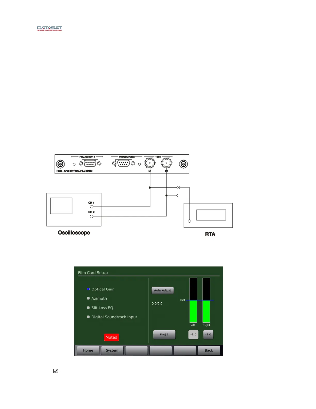
Connect the oscilloscope to the AP25 via the Left and Right BNC test connectors on the H338
optical card located on the back of the AP25. See Figure 9.
Figure 9 – Test connections
The Film Setup screen on the AP25 will be used during the alignment procedure. Go to Menu
(System) → Formats → Format Options → Film Options → Film Setup.
Figure 10 – Film Card Setup Screen
Note: When in the Film Card Setup screen, noise reduction (SR) is not active and all audio
outputs are muted. Changing to another screen will enable any noise reduction and un-mute