AP25 Installation and Operating Guide Page 90
AP25 Installation & Operating Guide Document # 9301H79500 Ver. 1.00
Set the crossover ID for easy identification. Here we set the crossover ID for channel 1 output L
which identifies it as the low frequency output for channel one (1). This is only a label for easy
identification and does not affect the crossover itself.
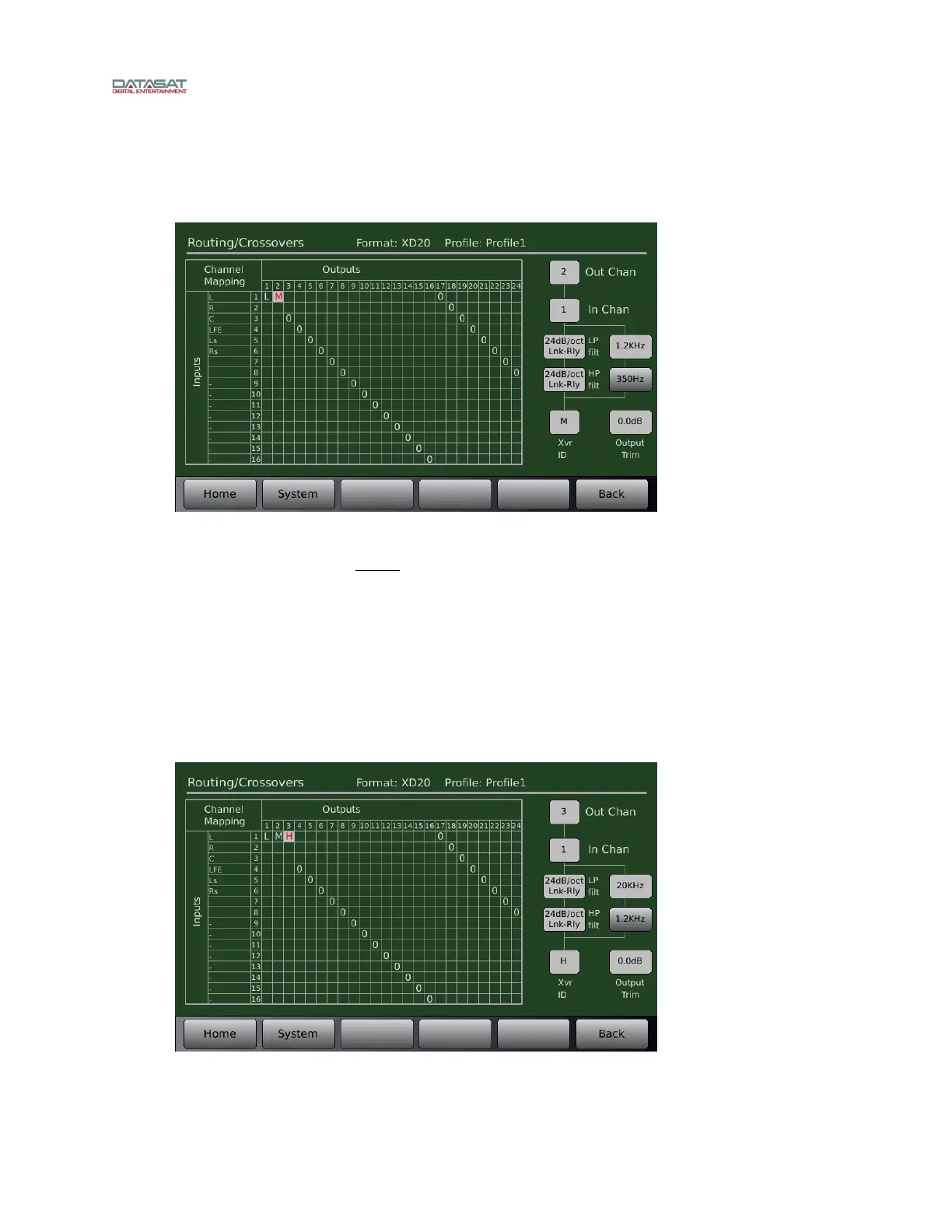
Mid Frequency
Figure 69. Example – Mid Frequency Crossover Setup
As shown in Figure 69, set output channel 2 for the mid range driver. Make sure the input
channel is still set to 1 (or left channel, remember, left = channel 1 in the example).
Set the low pass filter to the mid range driver’s upper crossover point, which in this case is
1200Hz.
Set the high pass filter to the mid range driver’s lower crossover frequency, which in this case is
350Hz.
Set the slope to 24dB/octave.
Set the crossover ID to M to identify it as the midrange frequency output for channel two (2).
High Frequency
Figure 70. Example – High Frequency Crossover Setup