1.8
1
INTRODUCTION
1.f SUMMARY OF LOGIC I/O FUNCTIONS
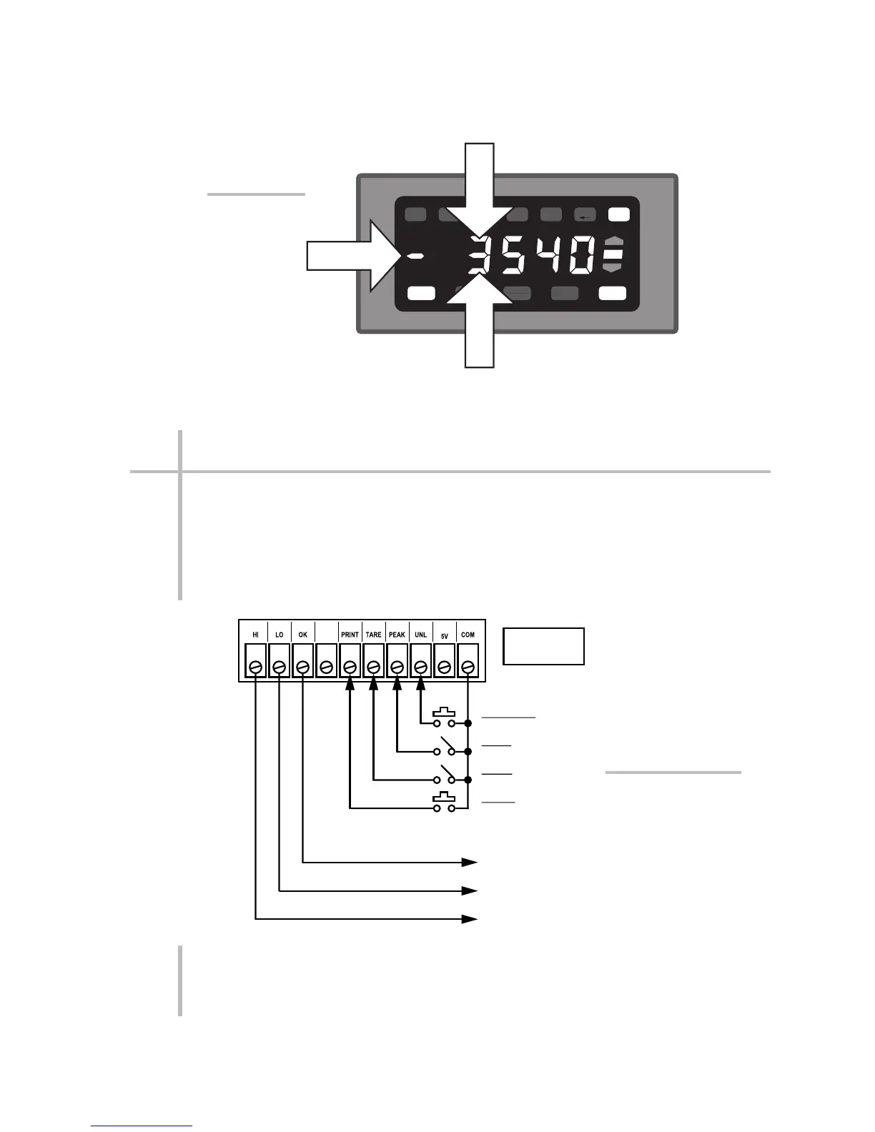
The rear-panel LOGIC I/O CONNECTOR provides seven active logic input/output
bits in open-collector, negative-true form, where the "Logic 1" state is defined as
nominal 0 V-DC and "Logic 0" as nominal +5 V-DC. The standard logic I/O config-
uration is shown in Fig. 5(a), below, with reference to the 10-terminal Logic I/O
Connector on the rear of the unit. For recommended logic interconnections, see
Section 2.e. Each I/O function is fully described in Appendix F.
PLEASE NOTE: THE MINIMUM TIME ALLOWED BETWEEN ACTIVATION AND
REACTIVATION OF ANY OF THE FOUR LOGIC CONTROL INPUTS IS 100 MIL-
LISECONDS.
1.f SUMMARY OF LOGIC I/O FUNCTIONS
SET UP
TARE
RESET
PRINT ENTER
HI
OK
LO
COM
RAN
FILTER ANO
DEC
LIMIT
Press top segment to
increment digit (up to "9")
Press bottom segment to
decrement digit (down to "0")
Press "–"
segment to
change polarity
Fig. 4 Use of
NUMERIC
BUTTONS in
SETUP MODE
LOGIC LOW
TO ENABLE
Logic Inputs:
Logic Outputs:
"LIVE" DATA IN
"LESS THAN" ZONE
"LIVE" DATA IN
"OK" ZONE
"LIVE" DATA IN
"GREATER THAN" ZONE
UNLATCH
PEAK
TARE
PRINT
*
Ground connections to
be provided by user.
See also Fig. 17(a).
*
+
Fig. 5(a)
Standard Logic
Inputs and Outputs

 Loading...