4.c.4 15-SEGMENT LINEARIZATION
NOTE: THIS CALIBRATION TECHNIQUE DOES NOT APPLY TO THE THERMO-
COUPLE CONDITIONER.
4.c.4.a INTRODUCTION
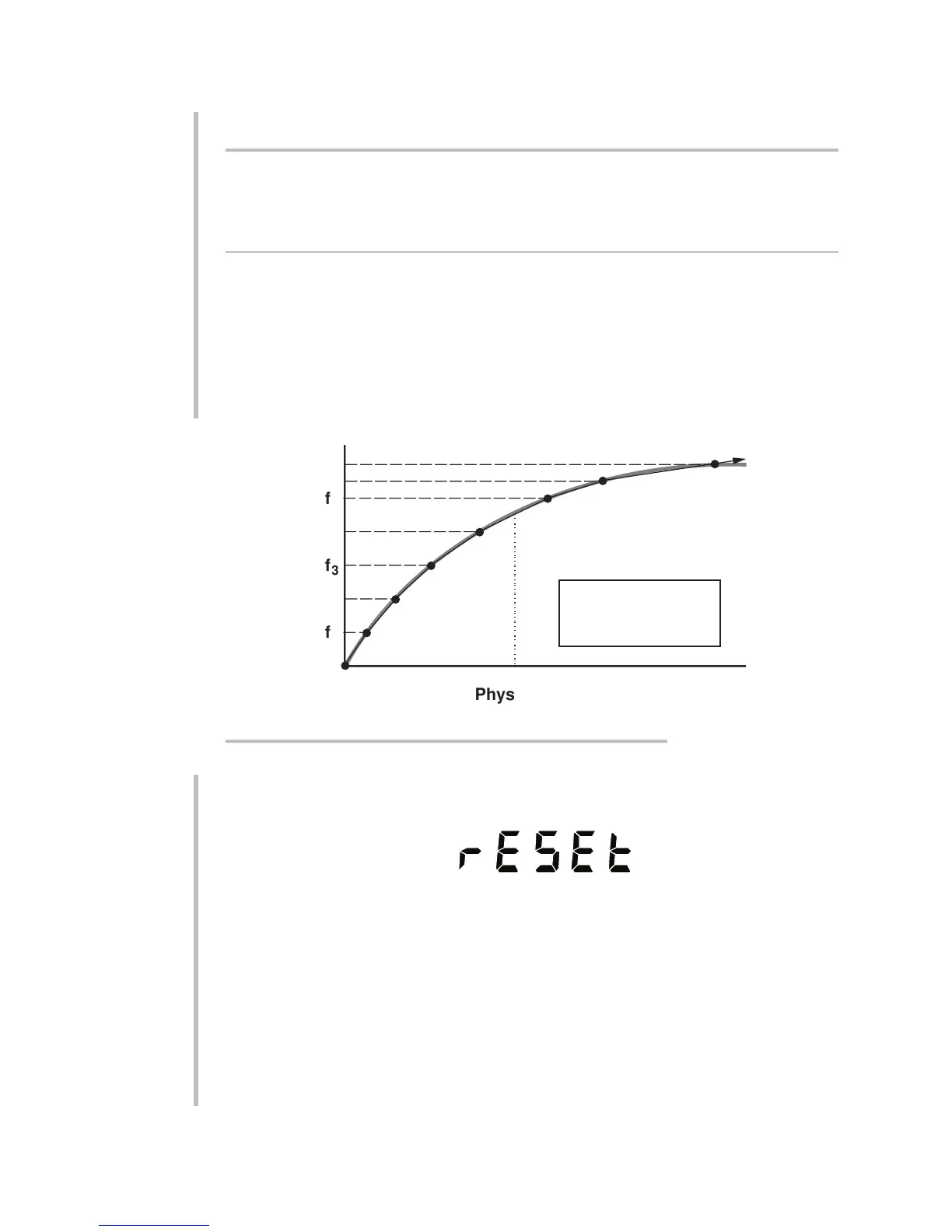
Whether you set up your internal linearization by directly entering input/output
values or by "forcing" each output value based on a corresponding value of actual
input loading, you should first divide your transducer's rated operating range into
a number of approximately equal segments (up to a total of fifteen). The more
nonlinear curve portions, however, may require shorter and more numerous lin-
earization segments, as with segments (f
5
to f
6
) and (f
6
to f
7
) in Fig. 21. Note also
that the final (or "highest") segment effectively extends in a straight line past the
last defined "endpoint" all the way to the end of the present full-scale range.
Once you have selected the "LINEARIZATION" calibration method as explained in
Section 4.c.1, above, the unit will display the word "RESET":
You now have the option of resetting the present linearization table. WHEN YOU
"RESET" THE TABLE, YOU ARE IN EFFECT INSTRUCTING THE 3500 INSTRUMENT
TO SET THE NUMBER OF ACTIVE LINEARIZATION SEGMENTS TO ZERO.
Note, however, that the endpoint definitions for each line segment in the existing
table are neither cancelled nor altered when the table is "reset." They will be
changed only when new input/output values are entered for the segment in ques-
tion— either directly or by "force." Until then, the segment's existing definition
remains in memory as it was prior to the table "reset," though it no longer has any
effect on calibration. As such, it is still accessible through the "READ" form of the
LINEARIZE (LIN) command, but not through the front panel. Thus, if you acciden-
tally reset the linearization table, any and all segment definitions that have not
4.12
4
SETUP: INSTRUMENT CALIBRATION
4.c CALIBRATING THROUGH THE FRONT PANEL
f
f
f
3
Physical Input
Displayed Output
1
f
2
f
4
5
f
6
f
7
z
i
Segment No. 1
Segment No. 2
Segment No. 3
Segment No. 4
Segment No. 5
Segment No. 6
Segment No. 7
Does not apply to
Thermocouple
Conditioner
Fig. 21 Typical Linearization Curve with Seven Segments
 Loading...
