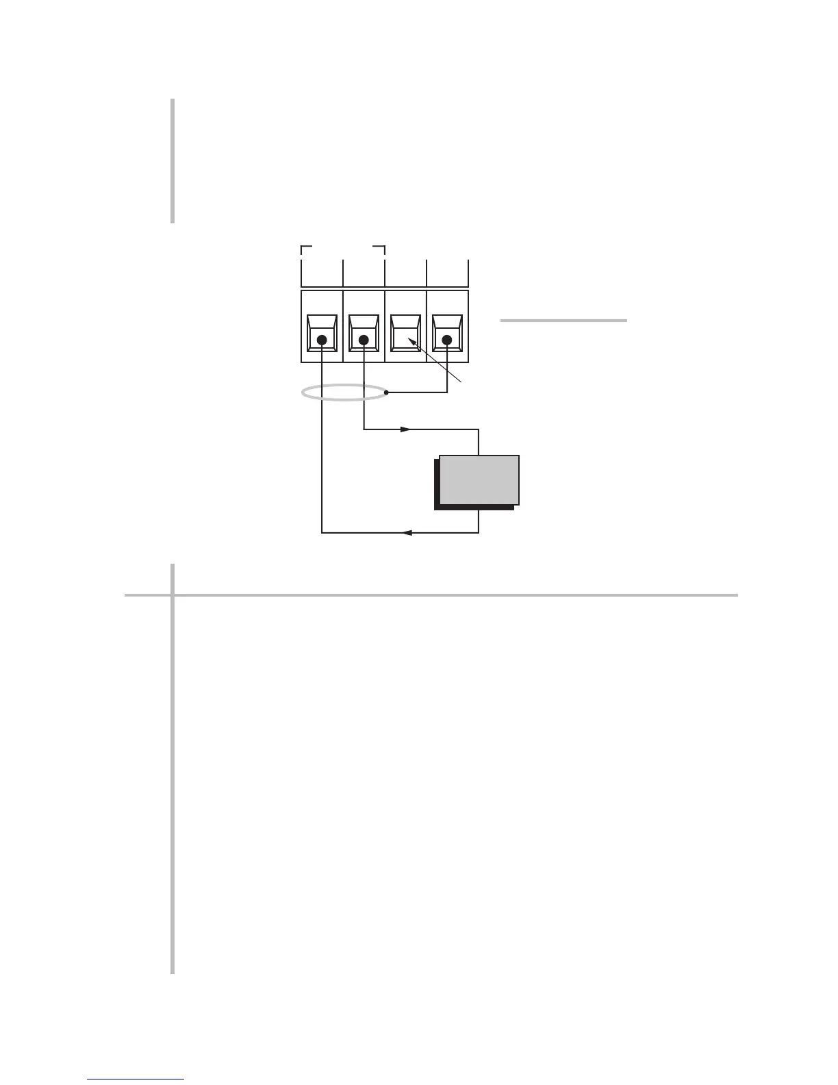
Fig. 16 shows how an external device connects to the ANALOG OUTPUT CON-
NECTOR on the rear of the conditioner, including the Models 3510 and 3540. The
output is single-ended, and returns to "SIGNAL COMMON" (i.e., GROUND).
For offsetting and scaling of the ANALOG OUTPUT, see Section 3.a.7. The fre-
quency characteristics and step-response settling time of the output will depend
on which pair of programming pins are jumpered. For details, see Appendix A.
2.e LOGIC INPUT/OUTPUT CONNECTIONS
The rear LOGIC I/O CONNECTOR is shown in Figs. 2 and 5(a). It has eight
labelled TTL/CMOS-compatible I/O terminals (one of which is normally unused),
plus a LOGIC REFERENCE terminal (+5 V) and a GROUND terminal (COM). In the
standard logic configuration described in Section 1.f and Appendix F, the first
three I/O terminals (left to right) are logic outputs, while the last four are logic
inputs. For the Model 3570 DC Strain Gage Conditioner (only), two logic inputs
("+" and "–") are also provided on the Analog Input Connector, for control of shunt
calibration—see Fig. 5(b). For complete logic-signal specifications, see Appendix
A.
Fig. 17 shows how to wire
a. negative-true logic INPUT to a given terminal from external switch contacts;
b. negative-true logic INPUT to a given terminal from an active TTL logic system
and open-collector logic OUTPUT from a given terminal to an active TTL logic
system;
c. negative-true logic INPUT to a given terminal from an INPUT CONTROL
BLOCK and open-collector logic OUTPUT from a given terminal to an isolated
POWER CONTROL BLOCK.
d. open-collector logic OUTPUT from a given terminal to drive an external relay
or TRIAC controller.
2.16
2
SETUP: CONNECTIONS AND POWERUP
2.e LOGIC INPUT/OUTPUT CONNECTIONS
EXTERNAL
DEVICE
+
–
Signal
Common
Signal
Shield
GND OUT
ANALOG
+5V
PWR
COM
This terminal not
currently used
Fig. 16 Analog Output
Connections
(ALL Conditioners)
 Loading...
