2.c RS-485 (“MULTINODE NETWORK”) CONNECTIONS
You can also set a 3500 Series instrument's RS-232/485 Interface Port for RS-485
intercommunications with a multidrop network of up to 99 independent Daytronic
signal conditioning instruments (3500 Series, 4000 Series with “N” Option, and/or
5000 Series)—all controlled by a supervisory computer with RS-232-C I/O. To do
so, YOU MUST ASSIGN THE 3500 INSTRUMENT A UNIQUE NONZERO NODE
NUMBER. You will be shown in Section 3.a.4 how to set the node number and
other necessary RS-485 communications parameters via the front-panel buttons.
IMPORTANT: BEFORE NETWORK INTERCONNECTIONS ARE ESTABLISHED,
YOU SHOULD SET UP EACH 3500 SERIES NETWORK "NODE" INDIVIDUALLY, BY
MEANS OF THE SETUP PROCEDURES GIVEN IN SECTIONS 3 AND 4.
While it is possible to make separate network "branches" issue from a single
node, such an arrangement can lead to less than optimum signal-to-noise ratio
because of unwanted reflections over interface lines. A strictly linear configura-
tion like that shown in Fig. 14(a) is therefore highly recommended.
For proper conversion of interface levels, you must attach a Model 5E485
RS232-to-RS485 Adaptor to the computer's RS-232-C port, via the Model 5E25
DB25 Male-to-Female Converter, as shown in Fig. 14(a).* The adaptor’s RS-
485 Interface Port should then connect directly to the RS-232/485 Interface Port
of the first network node—which should be a 3500 Series instrument—via the
cabling given in Fig. 14(b). Note that the +12-V supply of the first node (when it is
a 3500 instrument) is used to power the Model 5E485, as shown in Fig. 14(b).**
Fig. 14(c) shows the pin-to-pin cabling to be used between each pair of adjacent
3500 instrument nodes, or between a 3500 node and an adjacent 4000 Series
node. Interconnections between a 3500 or 4000 node and a separately powered
5000 node are shown in Fig. 14(d).
2.12
2
SETUP: CONNECTIONS AND POWERUP
2.c RS-485 (“MULTINODE NETWORK”) CONNECTIONS
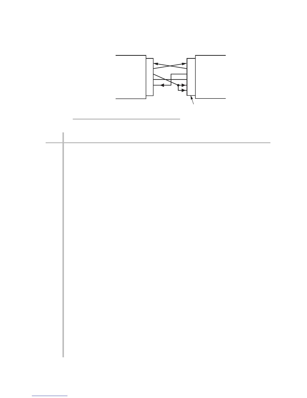
9-Pin RS-232-C
Connector
2
3
4
5
8
2
3
4
5
6
8
RECEIVE
TRANSMIT
DTR
COMMON
CTS
RECEIVE
TRANSMIT
DTR
COMMON
DSR
CTS
Computer
or other RS-232-C Device
Fig. 13 Suggested RS-232-C Interface
Connections (to 9-Pin RS-232-C Connector)
* The Model 5E25 is not necessary when the computer is equipped with a Model PC-HSICA
High-Speed Serial Interface Card. Also, you may use your own RS-232-to-RS-485 converter
in place of the Model 5E485, if desired. Converter connections will depend on whether there
are separate "XMIT" and "RCV" pairs or a single "485 DATA" pair. Contact the factory for
instructions.
** If the network contains one or more 5000 Series instrument nodes, a separate power source
of 10 to 40 V-DC (nominal 24 V-DC recommended) is required to power both the 5E485 and
the 5000 nodes—in which case the +12-V pin on every 3500 node should not be used. See any
5000 instrument instruction manual for details.
 Loading...
