For RS-485 communications, the relevant pins of the RS-232/485 Interface Port
are as follows:
Pin No. Function
1 485 DATA
5 COMMON (GND)
6 485 DATA
7 +12 V
9 SHIELD
RS-485 interconnections require Belden 8162 Datalene 100-Ω shielded cable (or
equivalent). THE INDICATED SHIELDING IS VERY IMPORTANT AND SHOULD BE
FOLLOWED CLOSELY.
For network chains of over 500 feet, the RS-232/485 Interface Port of the last
node in the sequence should be "terminated" by means of a 0.0047-µf capacitor
and a 100-Ω resistor across the two "DATA" terminals (again, see Fig. 14(a)).
2.13
SETUP: CONNECTIONS AND POWERUP
2
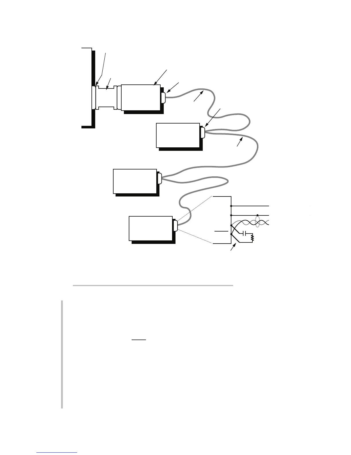
2.c RS-485 (“MULTINODE NETWORK”) CONNECTIONS
RS-485 Terminator
(for chains over 500 ft.)
Computer 25-Pin
RS-232-C Port
Model 5E485
RS232-to-RS485
Adaptor
Model 5E25
Male-to-Female
Converter*
Not required with
Model PC-HSICA
High-Speed Serial
Interface Card.
4-pin RS-485 Interface
& DC Power Port
Node RS-485 Interface
Port or Computer
Interface Port in RS-485
Communications Mode
For cabling,
see Fig. 14(b)
For cabling,
see Fig. 14(c)
Fig. 14(a) Connections for a Network of Three Instru-
ment Nodes (where the first is a 3500 Series instrument)
 Loading...
