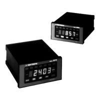
1.a USING THIS MANUAL
THIS MANUAL TREATS ALL SIX STANDARD MODELS BELONGING TO THE
DAYTRONIC 3500 INSTRUMENT SERIES. THESE MODELS ARE AS FOLLOWS:
• the Model 3510 Thermocouple Conditioner
• the Model 3530 AC LVDT Conditioner
• the Model 3540 Frequency Input Conditioner
• the Model 3560 Voltage Conditioner
• the Model 3570 DC Strain Gage Conditioner
• the Model 3578 AC Strain Gage Conditioner
EXCEPT WHERE OTHERWISE STATED, THE INFORMATION IN THIS MANUAL
APPLIES EQUALLY TO ALL SIX MODELS.
DESCRIPTIONS, PROCEDURES, AND OPERATIONS SPECIFIC TO A GIVEN
MODEL OR MODELS WILL BE CLEARLY IDENTIFIED AS SUCH.
1.b GENERAL INSTRUMENT DESCRIPTIONS
1.b.1 INTRODUCTION
Every 3500 Series instrument can be completely set up and operated either
through the front-panel keypad or via simple mnemonic commands received
from an external computer or terminal through its RS-232/485 Interface Port.
The instrument can transmit data from this port in response to an interrogation
from an external computer, or can send it to an RS-232 serial printer when the
PRINT button is pressed (assuming that it is set to RS-232 mode). When in RS-
485 mode, a given 3500 instrument can represent one of up to 99 data-collection
"nodes" of a high-speed multidrop network.
Features common to all models include
• continuous dual-limit monitoring with front-panel annunciation, programmable
hysteresis windows, and TTL-level logic control outputs
• front-panel security code
• real-time positive peak capture or track/hold operation
• user-settable automatic tare offset
• internal 15-segment linearization for calibration of nonlinear inputs (except for
the Model 3510 Thermocouple Conditioner)
• selectable digital filtering
• selectable analog filtering (except for the Model 3510 Thermocouple Condi-
tioner)
• scalable analog output to drive strip-chart recorders or other devices (it may
also be used as feedback for a PID control loop)
• data-transmission formatting options, including "header" and "tailer" character
strings, node-number "echo," and limit-status indication
1.1
INTRODUCTION
1
1.a USING THIS MANUAL 1.b GENERAL INSTRUMENT DESCRIPTIONS

 Loading...