2.d ANALOG OUTPUT CONNECTIONS
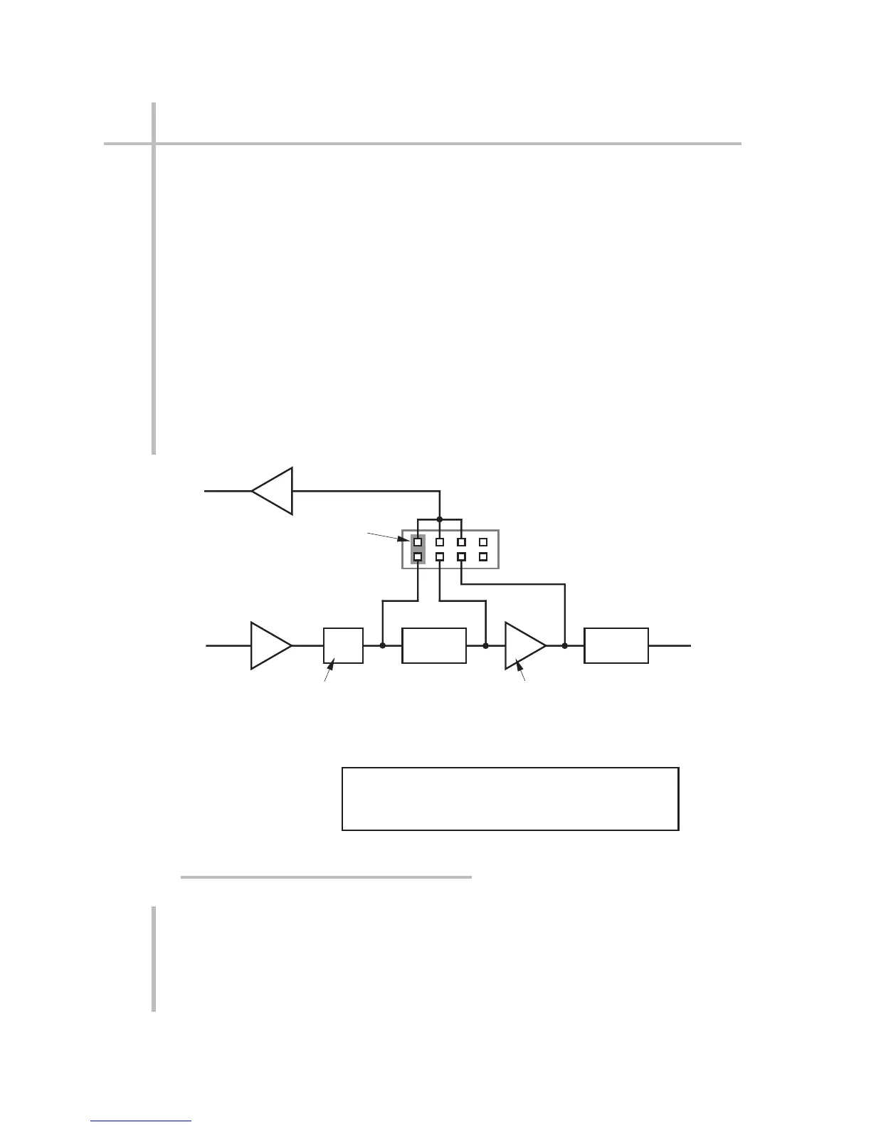
As indicated in Fig. 15, the ±5-V analog output signal of the Model 3530 LVDT
Conditioner, Model 3560 Voltage Conditioner, Model 3570 DC Strain Gage
Conditioner, or Model 3578 AC Strain Gage Conditioner may represent the
state of the conditioned input (A) after the FIXED ANALOG FILTER; (B) after analog
peak capture; or (C) after the SELECTABLE ANALOG FILTER (5/10/20 Hz for each
of these conditioners).* Each unit is initially set at the factory to source the analog
output after the FIXED ANALOG FILTER (Point A). To select a different source
point for any of these conditioners, you should
1. First turn OFF the unit and disconnect the power cord.
2. Remove the screw(s) holding the rear plate that covers the ANALOG OUTPUT
PROGRAMMING PINS (see Fig. 2(a) or 2(b)).**
3. Using needle-nose pliers, pull out the single Berg-Pin jumper and reposition it
on the pair of pins corresponding to the desired source (A, B, or C—again, see
Fig. 15). The pins labelled D are not currently used.
4. Replace the cover and reactivate the unit.
2.15
SETUP: CONNECTIONS AND POWERUP
2
2.d ANALOG OUTPUT CONNECTIONS
* For the Model 3540 Frequency Conditioner, the SELECTABLE ANALOG FILTER is 2.5/5/10 Hz;
for the Model 3510 Thermocouple Conditioner, there is no SELECTABLE ANALOG FILTER. The
3510’s ANALOG OUTPUT is taken directly from the DIGITAL/ANALOG CONVERTER; the 3540’s
ANALOG OUTPUT is always taken from souce "C" in the figure.
** The Model 3578 AC Strain Gage Conditioner has only one screw; the others have two.
Analog Output
Analog Input
+PEAK A/D
Analog Output
Programming Pins
(see Fig. 2)
A
Berg-Pin Jumper
(connect one pair only)
BCD
ABC
Fixed Analog Filter:
Model 3530 LVDT Conditioner: 100 Hz
Model 3560 Voltage Conditioner: 2000 Hz
Model 3570 DC Strain Gage Conditioner: 2000 Hz
Model 3578 AC Strain Gage Conditioner: 20 Hz
Selectable Analog Filter:
5/10/20 Hz
This diagram does not apply to the Models
3510 and 3540, which do not have Analog
Output Programming Pins.
Fig. 15 Analog Output Programming Pins
 Loading...
