1.c PHYSICAL LAYOUT
Study the following diagrams to acquaint yourself with the most important front
and rear elements.
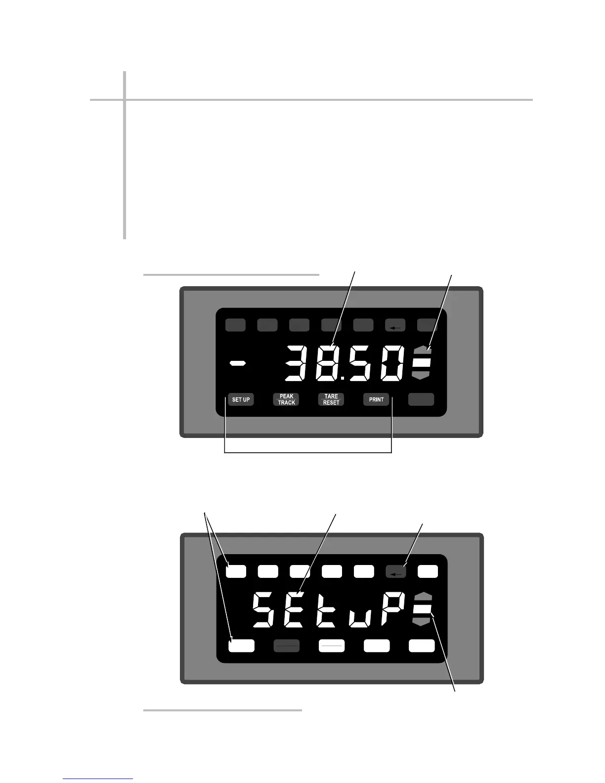
Fig. 1(a) shows a typical "RUN-TIME" display, with "live" data and limit-status
annunciation. Note the four front-panel buttons that are active (but not necessari-
ly lit) during normal run-time operation. For a full description of run-time button
functions, see Appendix E.
Fig. 1(b) shows a typical SETUP display—specifically, the display that appears
after the security code has been entered and the unit is ready for any of the front-
panel setup procedures given in Sections 3.a and 4.a.
1.4
1
INTRODUCTION
ENTER
HI
OK
LO
COM
RANGE
CAL FILTER ANO
DEC
LIMIT
"Live" Limit
Status Indicators
"Live" Data
Display
Active Run-Time Buttons
Fig. 1(a) Typical “Run-Time” Display
SET UP
PEAK
TRACK
TARE
RESET
PRINT ENTER
HI
OK
LO
COM
RANGE
CAL FILTER ANO
DEC
LIMIT
"DEC" button lights when
decimal-point location of
setup parameter can be
changed
Limit Status Indicators
updated with every change
of the display
Setup message or
parameter value
Active Setup
Buttons are lit
1.c PHYSICAL LAYOUT
Fig. 1(b) Typical “Setup” Display
 Loading...
