PRELIMINARY
B. To Access Burner Orifices/Jets:
Unscrew the orifice using an appropriately
sized conventional socket or nut driver. Use a
piece of sticky tape in socket to prevent the
loose orifice from falling out.
Verify that the orifices in the kit match the chart
sizes and replace the orifices.
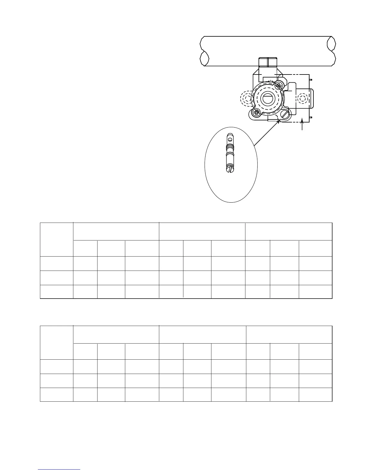
C. To Access Valve Bypass Jets:
Remove the c-clips that retain the valve
switches and slide the switches off of the valve
shafts. Locate the valve bypass jet in the valve
body. Using a small 1/8″ flat-blade screwdriver,
carefully remove the valve bypass jets.
Replace each orifice with the marked orifice
from the kit. Ensure that the replaced orifice is
firmly seated in the valve.
Valve Switch
(Remove)
ORIFICE SIZES – NATURAL GAS
LOCATION MAIN SIMMER (LOW)
SIMMER (LOW)
VALVE ORIFICE (SIMMER)
SIZE MARKING RATE SIZE MARKING RATE SIZE MARKING RATE
REAR 1.51mm 151 11K Btu/hr 0.57mm P 3000 Btu/hr 0.71mm 71 1200 Btu/hr
FRONT 1.51mm 151 11K Btu/hr 0.57mm P 3000 Btu/hr 0.71mm 71 1200 Btu/hr
CENTER 2.0mm 200 17.5K Btu/hr 0.57mm P 3000 Btu/hr 0.71mm 71 1200 Btu/hr
ORIFICE SIZES – LP GAS
LO CAT ION
MAIN
VALVE ORIFICE (SIMMER)
SIZE MARKING RATE SIZE MARKING RATE SIZE MARKING RATE
REAR 0.89mm 89 10K Btu/hr 0.37mm G 3000 Btu/hr 0.45mm 45 1200 Btu/hr
FRONT 0.89mm 89 10K Btu/hr 0.37mm G 3000 Btu/hr 0.45mm 45 1200 Btu/hr
CENTER 1.10mm 110 15K Btu/hr 0.37mm G 3000 Btu/hr 0.45mm 45 1200 Btu/hr