G3
™
User’s & Installation Manual
7/October/2020
71
Appendix A: Communications Port
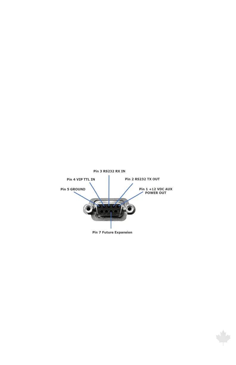
A RS232 communications port is located on the rear panel of the
computer unit. The pinout of the DB-9 serial connector is:
Pin 1: +12 VDC auxiliary power out.
Pin 2: RS232 transmit out of G3™ radar.
Pin 3: RS232 receive into the G3™ radar.
Pin 4: VIP (Vehicle Interface Protocol GEN 2) input into G3™ radar.
Pin 5: Signal/power ground.
Pin 6: No connection.
Pin 7: Speedometer pulse input.
Pin 8: No connection.
Pin 9: No connection.
Figure A
Serial port pin out