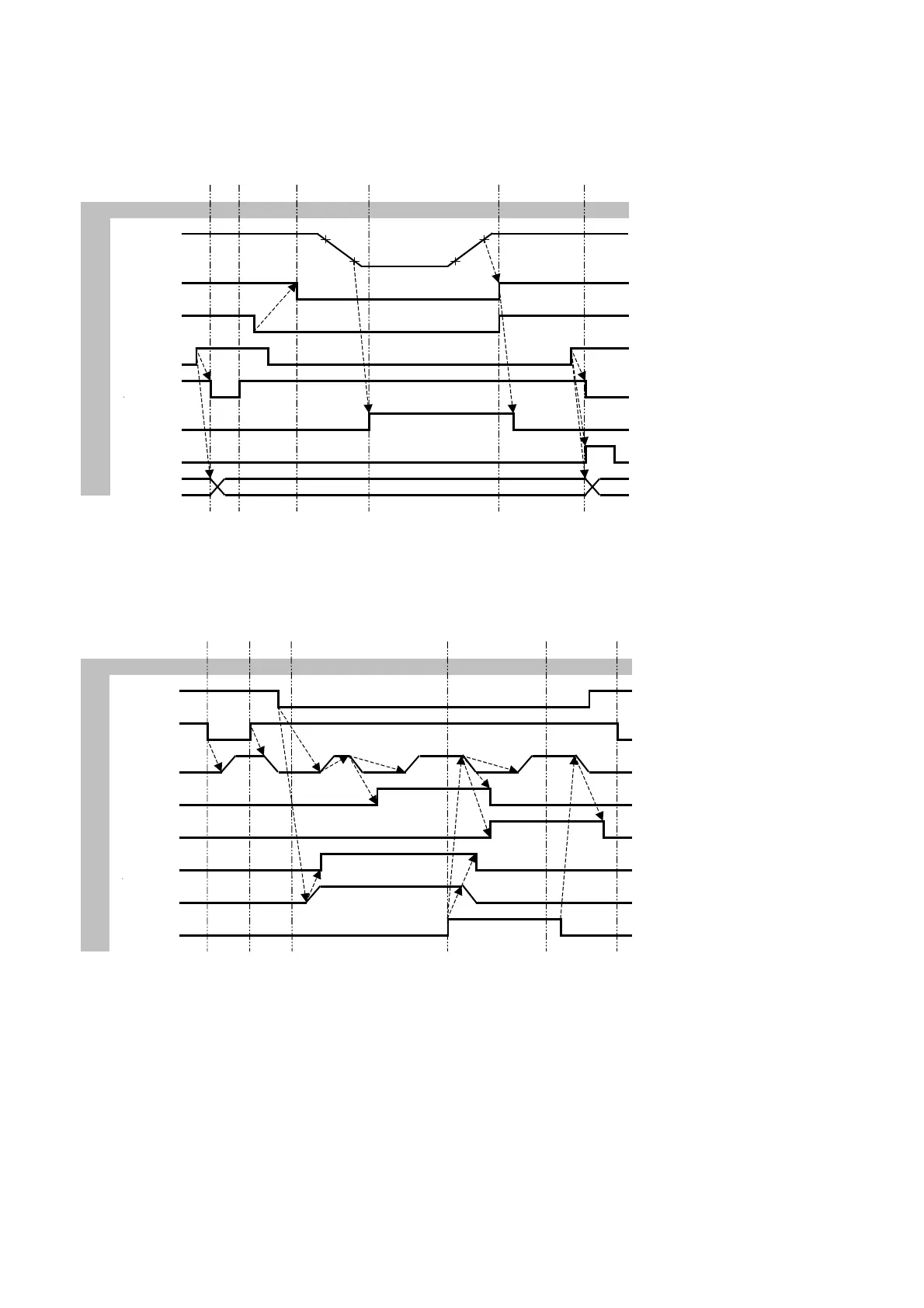
Timing diagrams
DAC-360 with stroke potentiometer
S0 = Controller Stopped
Status S1 S2 S3 S4 S5 S1 S1 = Positioning
S2 = Wait for ST low
inp Stroke-pot S3 = Wait for EOS
*S4 = Wait for UDP
S5 = Wait for ST high
out UDP
T6+T5+½T1 T1 = Delay before cutting force
inp PEDAL T5 = Clamping time
T6 = Delay before main clamping force
inp ST
* = UDP high only if UDPIN high in case of:
out RDY
gauge position inside safety zone o
Angle needs adjustment
out EOS in case of combined potentiomete
out EOC
out FD
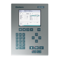
DAC-360 pressure outputs
S0 = Controller Stopped
Status S1 S2 S3 S4 S5 S1 S1 = Positioning
S2 = Wait for ST low
inp PEDAL S3 = Wait for EOS
S4 = Wait for UDP
out RDY S5 = Wait for ST high
T6 p2 T1 T3
out P-main p1 T5 p3 p4 T1 = Delay before cutting force
½T1 ½T3 T2 = Delay before clamping force
out B_DN ½T4 T3 = Delay before opening
½T3 T4 = Delay before Angle/Gap force
out B_UP T5 = Clamping time
T6 = Delay before main clamping force
out CLAMP
T2 p1 = Angle/Gap force
out P-clamp p5 p2 = Main clamping force
p3 = Cutting force
out EOS p4 = Opening force
p5 = Clamping force