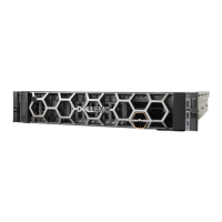
Figure 56 Slide the system into the cabinet
Connect the I/O cables and power cords
This procedure is used to connect the peripherals and power to the system.
Procedure
1. Using the connection information recorded on the labels, connect the I/O cables to the
system.
2. Plug the power cords into the power supplies.
Verifying successful NIC replacement from the ACM
After the NIC is replaced and power has been re-applied, you can run the FRU command line
verification from the ACM to ensure that the replacement was successful.
Procedure
1. From the ACM, type the following command: # showfru network
The screen displays that the system is collecting data. When the data collection is
completed, the screen displays status information for ports the NIC.
acme-dp4400-ACM:~ # showfru network
Collecting Data............
______________________________________________________________________________
| Name | Port| Link Status| Model Name |
|=============================================================================|
| NIC Integrated 1| 1 | Up | Ethernet 10G 4P X710 SFP+ rNDC |
| NIC Integrated 1| 2 | Up | Ethernet 10G X710 rNDC |
| NIC Integrated 1| 3 | Down | Ethernet 10G X710 rNDC |
| NIC Integrated 1| 4 | Down | Ethernet 10G X710 rNDC |
| NIC Slot 1 | 1 | Down | Ethernet Converged Network Adapter X710|
| NIC Slot 1 | 2 | Down | Ethernet Converged Network Adapter X710|
| NIC Slot 1 | 3 | Down | Ethernet Converged Network Adapter X710|
| NIC Slot 1 | 4 | Up | Ethernet Converged Network Adapter X710|
| NIC Slot 2 | 1 | Up | Gigabit 2P I350-t Adapter |
Remove and replace assemblies
70 Dell EMC Integrated Data Protection Appliance DP4400 Service Procedures

 Loading...

