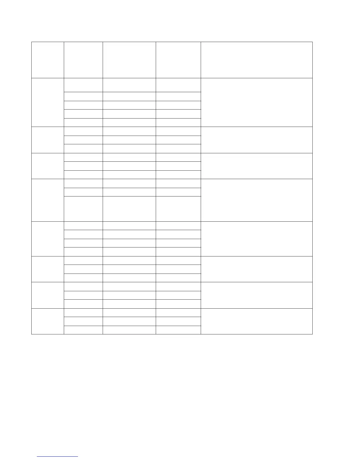
5-8 Service Manual
J502 1, 3, 5, 7, 11,
13, 15
5V dc LVPS - Engine Board
45 Vdc
6 24 V dc
17, 19 24 V dc
Other 0 V dc
J503 11, 13 15 5V dc HVPS - Engine Board
17, 19 24V dc
10,12,14,16,18 Ground
J37 11, 13 15 5V dc PS (LVPS/HVPS) - Controller Board
17, 19 24V dc
10,12,14,16,18 Ground
J30 3, 4 +14V AFE (CCD Ribbon) - Controller Board
6, 7 +5V
1,5,13,15,18,
21,24,27,30,
31-36
GND
J28 1 V12_A- FB Motor - Controller Board
2 V12_A
3 V12_B-
4 V12_B
J17 14 +5V ADF - Controller Board
11, 12 +24V
3,5,8,10,13 GND
J13 1 +5V Home Sensor - Controller Board
2GND
3HOME
J12 1 GND Paper Length (FB) - Controller Board
2 P_LENGTH
3+5V
Connector Pin # Value
cable plugged
Value
cable unplugged
(if different)
Comments
 Loading...