3. SATA 6 Gbps drive connector (HDD1) 4. SATA 6 Gbps drive connector (HDD2)
5. Power-supply connector (ATX1) 6. Solid-state drive slot (M.2 PCIe SSD-2)
7. Solid-state drive slot (M.2 PCIe SSD-1) 8. Memory-module slot, DIMM1
9. Memory-module slot, DIMM2 10. CPU socket
11. PCI-Express x16 mechanical/x16 electrical slot (SLOT1) 12. PCI-Express x4 slot (SLOT3)
13. PCI-Express x4 slot (SLOT2) 14. Rear-chassis fan connector (FAN SYS1)
15. Rear-chassis fan LED connector (LED FAN SYS1) 16. Liquid cooling pump fan connector (FAN PUMP)
17. Liquid-cooling pump LED connector 18. Top-chassis fan connector one (FAN_SYS4)
19. Power-supply connector (ATX3) 20.Power-supply connector (ATX2)
21. Air-cooling fan connector (FAN CPU) 22.Top-chassis fan connector two (FAN_SYS5)
23. SATA power connector (SATA PWR) 24.Wireless-card slot
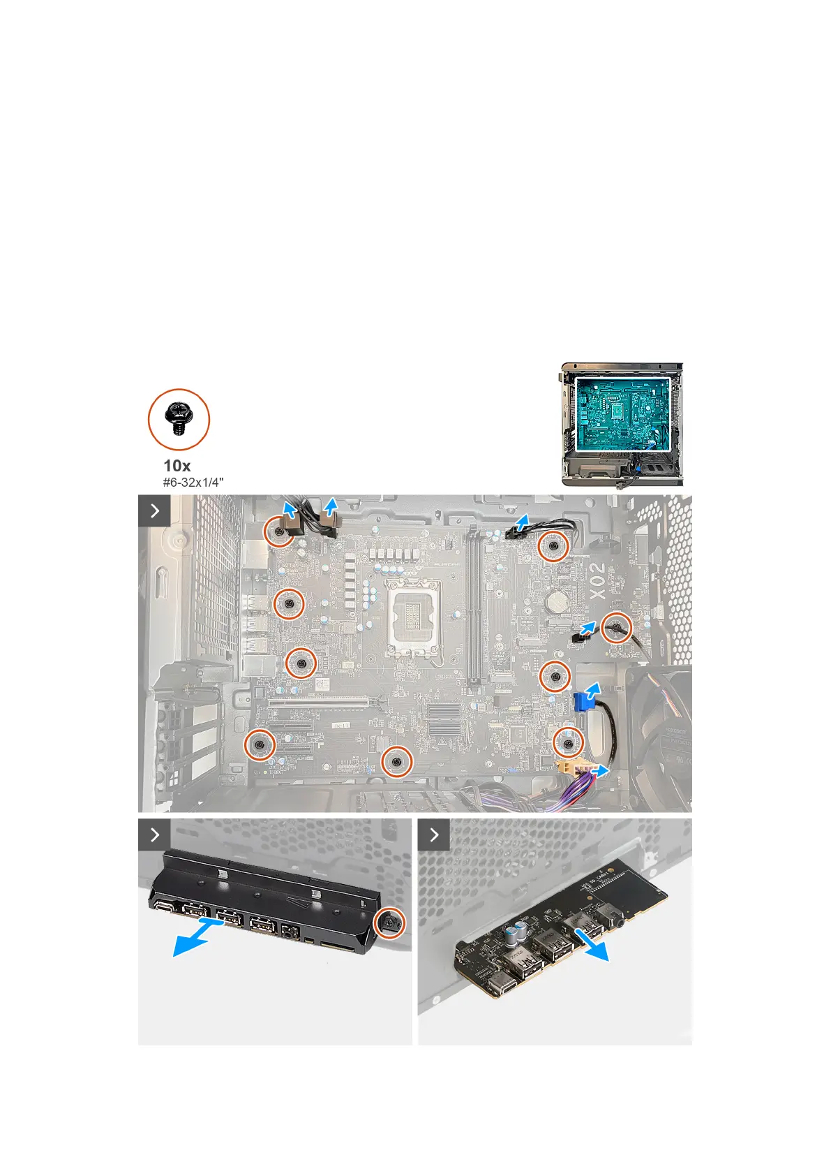
25.Front I/O-panel cable
The following images indicate the location of the system board and provide a visual representation of the removal procedure.
92