36 | Installing DC Power Supplies
www.dell.com | support.dell.com
5 Secure the chassis ground connection first:
Remove one outer nut and one washer from each of the six studs. One nut should remain, tight on the stud. If the
inner nut is loose, re-tighten it to 25 inch/lbs. maximum.
Locate the chassis ground connector studs on the PEM front panel (see
Figure 8-3
). The two rightmost studs are the
ground connection.
Install the grounding cable onto the ground studs. The grounding cable must comply with your local electrical codes
in size and color (typically the color is green or green with yellow stripe).
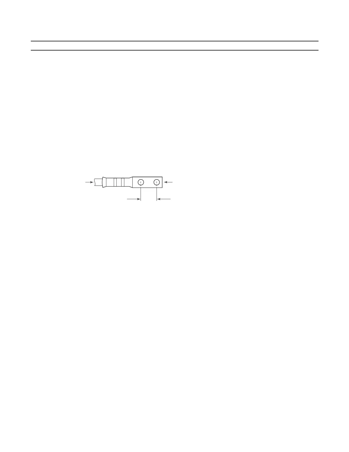
NOTE: Grounding cables must be terminated only with a UL-listed 2-hole lug with 1/4-inch holes on 3/4-inch
spacing (see
Figure 8-4
).
Replace the two washers and nuts on the studs.
With a 7/16-inch box or socket wrench, tighten the nuts (torque should not exceed 25inch/lbs).
Connect the opposite end of the grounding cable to the nearest appropriate facility grounding post.
Figure 8-4. Cable Connector Required for E1200 PEM
6 Connect the -48 VDC and Return cables from each PEM to the remote power sources (circuit breakers A and B).
Check that the remote power sources (for example, circuit breakers) are in the OFF position.
Locate the appropriate studs on the PEM front panel (
Figure 8-3
).
The two leftmost studs on the PEM are the -48 VDC (-) connection. The cable attached to these studs is typically
black.
• The two middle studs are the return (+) connection. The cable attached to these studs is typically red.
Install the -48 VDC and Return cables on the studs. The cables should be of the size and color to comply with local
electrical codes.
Note: Power cables must be terminated only with a UL-listed 2-hole lug with 1/4-inch studs with 3/4-inch spacing
(
Figure 8-6
).
Replace the washers and nuts on the studs.
With a 7/16-inch box or socket wrench, tighten the nuts.
Step Task (continued)
0.750"
High-strand-count
conductor
diameter
2 Holes
All measurements shown in inches.
fn00105lp
0.267