Do you have a question about the Dell Latitude E6420 and is the answer not in the manual?
Essential safety guidelines and conditions before starting computer servicing procedures.
List of tools required for performing computer maintenance and repair tasks.
Procedure for safely shutting down and powering off the computer before servicing.
Steps to reconnect external devices and cables after completing computer servicing.
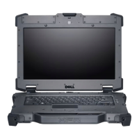
Step-by-step instructions for removing the ATG handle from the computer.
Step-by-step instructions for installing the ATG handle onto the computer.
Procedure for removing the ATG port cover from the computer's exterior.
Procedure for reinstalling the ATG port cover onto the computer.
Steps to remove the modem connector plug from the computer's chassis.
Steps to install the modem connector plug into the computer's chassis.
Procedure for safely removing an ExpressCard from its slot.
Procedure for safely installing an ExpressCard into its slot.
Detailed steps for safely removing the laptop's main battery.
Detailed steps for safely installing the laptop's main battery.
Instructions for removing the Subscriber Identity Module (SIM) card.
Instructions for installing the Subscriber Identity Module (SIM) card.
Procedure for removing the Secure Digital (SD) card from the computer.
Procedure for installing the Secure Digital (SD) card into the computer.
Steps to remove the bottom base cover of the computer.
Steps to reinstall the bottom base cover of the computer.
Detailed steps for safely removing the computer's hard drive.
Detailed steps for safely installing the computer's hard drive.
Procedure for removing the optical drive from the computer bay.
Procedure for installing the optical drive into the computer bay.
Steps for removing the memory module from the system board.
Steps for installing the memory module onto the system board.
Procedure for removing the Wireless Local Area Network (WLAN) card.
Procedure for installing the Wireless Local Area Network (WLAN) card.
Procedure for removing the Wireless Wide Area Network (WWAN) card.
Procedure for installing the Wireless Wide Area Network (WWAN) card.
Steps to remove the coin-cell battery from the computer.
Steps to install the coin-cell battery into the computer.
Procedure for removing the heat sink assembly from the system.
Procedure for installing the heat sink assembly onto the system.
Steps to remove the Bluetooth card from its holder.
Steps to install the Bluetooth card into its holder.
Procedure for removing the keyboard trim piece.
Procedure for installing the keyboard trim piece.
Detailed steps for safely removing the computer's keyboard.
Detailed steps for safely installing the computer's keyboard.
Steps to remove the modem card from its slot.
Steps to install the modem card into its slot.
Procedure for removing the palm rest assembly.
Procedure for reinstalling the palm rest assembly.
Steps to remove the smart card reader component.
Steps to install the smart card reader component.
Procedure for removing the media board from the computer.
Procedure for installing the media board onto the computer.
Procedure for removing the ExpressCard cage from the system.
Procedure for installing the ExpressCard cage onto the system.
Detailed steps for safely removing the computer's main system board.
Detailed steps for safely installing the computer's main system board.
Procedure for removing the audio speakers from the computer.
Procedure for installing the audio speakers into the computer.
Steps to remove the modem connector from the computer.
Steps to install the modem connector onto the computer.
Procedure for removing the Input/Output (I/O) board.
Procedure for installing the Input/Output (I/O) board.
Steps to remove the DC-in power port from the computer.
Steps to install the DC-in power port onto the computer.
Procedure for removing the entire display assembly from the computer.
Procedure for installing the entire display assembly onto the computer.
Procedure for removing the display hinge covers.
Procedure for installing the display hinge covers.
Procedure for removing the display bezel from the screen assembly.
Procedure for installing the display bezel onto the screen assembly.
Steps to remove the display panel from the display assembly.
Steps to install the display panel into the display assembly.
Procedure for removing the display panel mounting brackets.
Procedure for installing the display panel mounting brackets.
Steps to remove the integrated camera module.
Steps to install the integrated camera module.
Details on chipset, CPU types, memory, and bus specifications.
Specifications for audio, video hardware, and network adapters.
Details on display size, resolution, and available ports.
Specifications for keyboard layout, touchpad area, and battery types.
Introduction to System Setup and how to enter the BIOS settings.
Description of various configuration options available in System Setup.
Troubleshooting guide for LED codes indicating system errors.
Explanation of battery status lights and their meanings.
Interpretation of device status lights on the computer.
Information on how to contact Dell for sales and technical support.
| Bus type | DMI |
|---|---|
| Stepping | J1 |
| Tjunction | 100 °C |
| Processor cache | 3 MB |
| Processor cores | 2 |
| Processor model | i5-2410M |
| System bus rate | 5 GT/s |
| Processor family | Intel® Core™ i5 |
| Processor series | Intel Core i5-2400 Mobile Series |
| Processor socket | BGA 1023 |
| Processor threads | 4 |
| Processor codename | Sandy Bridge |
| Processor frequency | 2.3 GHz |
| Processor cache type | Smart Cache |
| Processor lithography | 32 nm |
| Processor manufacturer | Intel |
| Processor front side bus | - MHz |
| PCI Express slots version | 2.0 |
| Processor boost frequency | 2.9 GHz |
| Processor operating modes | 64-bit |
| ECC supported by processor | No |
| PCI Express configurations | 1x8, 1x16, 2x4, 2x8 |
| Thermal Design Power (TDP) | 35 W |
| CPU multiplier (bus/core ratio) | 23 |
| Maximum number of PCI Express lanes | 16 |
| Motherboard chipset | Intel® QM67 Express |
| HDD speed | 7200 RPM |
| HDD interface | SATA |
| Optical drive type | DVD-RW |
| Card reader integrated | Yes |
| Total storage capacity | 500 GB |
| Number of HDDs installed | 1 |
| Display diagonal | 14 \ |
| Display resolution | 1600 x 900 pixels |
| Native aspect ratio | 16:9 |
| Memory slots | 2x SO-DIMM |
| Internal memory | 4 GB |
| Memory clock speed | 1333 MHz |
| Internal memory type | DDR3-SDRAM |
| Maximum internal memory | 8 GB |
| Memory layout (slots x size) | 2 x 2 GB |
| On-board graphics card ID | 0x116 |
| Discrete graphics card model | - |
| On-board graphics card model | Intel® HD Graphics 3000 |
| On-board graphics card family | Intel® HD Graphics |
| On-board graphics card base frequency | 650 MHz |
| On-board graphics card dynamic frequency (max) | 1200 MHz |
| Type | PC |
| Compliance industry standards | IEEE 802.3, IEEE 802.3u, IEEE 802.3ab |
| Keyboard layout | QWERTY |
| Pointing device | Touchpad |
| Bluetooth version | 3.0+HS |
| Cabling technology | 10/100/1000Base-T(X) |
| Networking features | Gigabit Ethernet, WLAN |
| Operating system installed | Windows 7 Professional |
| Charging port type | DC-in jack |
| USB 2.0 ports quantity | USB 2.0 ports have a data transmission speed of 480 Mbps, and are backwards compatible with USB 1.1 ports. You can connect all kinds of peripheral devices to them. |
| CardBus PCMCIA slots quantity | 0 |
| Battery capacity | 60 Wh |
| Number of battery cells | 6 |
| Sustainability certificates | EPEAT Gold, ENERGY STAR |
| Product color | Black, Silver |
| Processor ARK ID | 52224 |
| Processor package size | 37.5x37.5 (rPGA988B); 31 x 24 (BGA1023) mm |
| Supported instruction sets | AVX |
| Intel Identity Protection Technology version | 1.00 |
| Depth | 241 mm |
|---|---|
| Width | 352 mm |
| Weight | 2070 g |
| Height (rear) | 32.4 mm |
| Height (front) | 26.9 mm |